Probe measuring device

A measuring device and stylus technology, applied in the direction of measuring devices, mechanical measuring devices, mechanical devices, etc., can solve the problems of poor measurement accuracy, wear of contact surfaces, gaps, etc., to ensure the straightness of movement and prevent partial wear Effect

Inactive Publication Date: 2012-08-15
ULVAC INC
View PDF1 Cites 2 Cited by
  • Summary
  • Abstract
  • Description
  • Claims
  • Application Information

AI Technical Summary

Problems solved by technology

[0005] However, in the static pressure type guide, after a certain period of use, wear of the guide surface of the guide rail and the contact surface of the linear motion bearing occurs, creating a gap between the two
In addition, the Y-axis table is displaced in the vertical direction by the amount of the gap, and the vertical position of the support part for the stylus provided on the Y-axis table deviates from the normal position, which deteriorates the measurement accuracy.

Method used


Image

  • Probe measuring device
  • Probe measuring device
  • Probe measuring device

Examples


Embodiment Construction

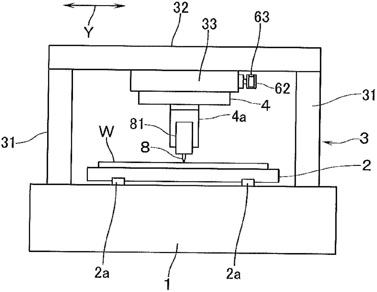
[0022] figure 1 A stylus type measuring device according to an embodiment of the present invention is shown. This measuring device has: a base 1; a sample table 2 for placing a test object W placed on the base 1; and a door-shaped frame 3 arranged on the base 1 so as to straddle the sample table 2 . When two horizontal directions perpendicular to each other are defined as the X-axis direction and the Y-axis direction, the sample stage 2 is movably supported on a pair of guide rails 2a, 2a whose longitudinal direction is in the X-axis direction and fixed on the base 1. . And, the rotation of the ball screw in the X-axis direction in the longitudinal direction, not shown, is used to move the sample table 2 in the X-axis direction through the nut screwed on the ball screw, so that the door-shaped frame 3 is relatively The measured object W moves relatively in the X-axis direction.

[0023] The door-shaped frame body 3 has pillars 31 and 31 erected on both sides of the base 1 ...


PUM


Abstract

A probe measuring device in which a probe is supported by a Y-axis stage (4) supported via a linear guide by a beam (32) at the top of a portal frame that moves freely in the X-axis direction relative to an object to be measured, wherein deterioration in measurement accuracy due to abrasion of the linear guide is prevented. The linear guide is composed of a pair of guide rails (51, 52) fixed to the undersurface of the beam (32), and a pair of linear-motion bearings (53, 54) that come into moveable contact with guide surfaces (51a, 52a), which are inclined relative to the vertical plane of the guide rails (51, 52). One of the linear-motion bearings (54) is made to float freely in the X-axis direction and the vertical direction relative to the Y-axis stage (4). An urging means (55), which urges the linear-motion bearing (54) in the X-axis direction in such a manner as to press the bearing against the guide surface (52a) of the guide rail (52), is disposed on the Y-axis stage (4), a second urging means (56), which urges the linear-motion bearing (54) downward, is disposed on the beam (32) side, and the direction of the vector of the resultant force of the urging forces of both urging means (55, 56) is thereby made to coincide with the normal direction of the guide surface (52a).

Description

technical field [0001] The present invention relates to a stylus-type measuring device for measuring the surface shape of an object to be measured, which has a stylus that contacts the surface of the object to be measured. Background technique [0002] Conventionally, there is known a stylus-type measuring device that uses two horizontal directions perpendicular to each other as the X-axis direction and the Y-axis direction, and has the ability to move relatively freely in the X-axis direction with respect to the object to be measured. The door-shaped frame; the Y-axis table that moves freely in the Y-axis direction is supported by the beam in the Y-axis direction at the upper end of the frame through the linear guide; the contact that will be used to contact the surface of the measured object The needle is supported on a Y-axis stand (for example, refer to Patent Document 1). [0003] In addition, in the structure described in Patent Document 1, the linear guide adopts a s...

Claims


Application Information

Patent Timeline
Patent Type & Authority Applications(China)
IPC IPC(8): G01B5/008G01B5/00
CPCG01B5/008G01B21/045G01B5/28G01D11/30
Inventor 柴智志佐藤诚一矢作充
Owner ULVAC INC
Why Eureka
Try Eureka