Method for assembling a blade to a cylinder body, blade, cylinder body and cutting device

A cylinder and blade technology, applied in textiles and papermaking, textile material cutting, metal processing, etc., to achieve the effect of reducing costs and materials

Inactive Publication Date: 2012-08-22
好使有限责任公司和两合公司
View PDF8 Cites 5 Cited by
  • Summary
  • Abstract
  • Description
  • Claims
  • Application Information

AI Technical Summary

Problems solved by technology

That is to say that, in addition to the puller itself, the support involves parts that are permanently installed in the cutting device, for which they must be remanufactured for each cutting d...

Method used


Image

  • Method for assembling a blade to a cylinder body, blade, cylinder body and cutting device
  • Method for assembling a blade to a cylinder body, blade, cylinder body and cutting device
  • Method for assembling a blade to a cylinder body, blade, cylinder body and cutting device

Examples


Embodiment Construction

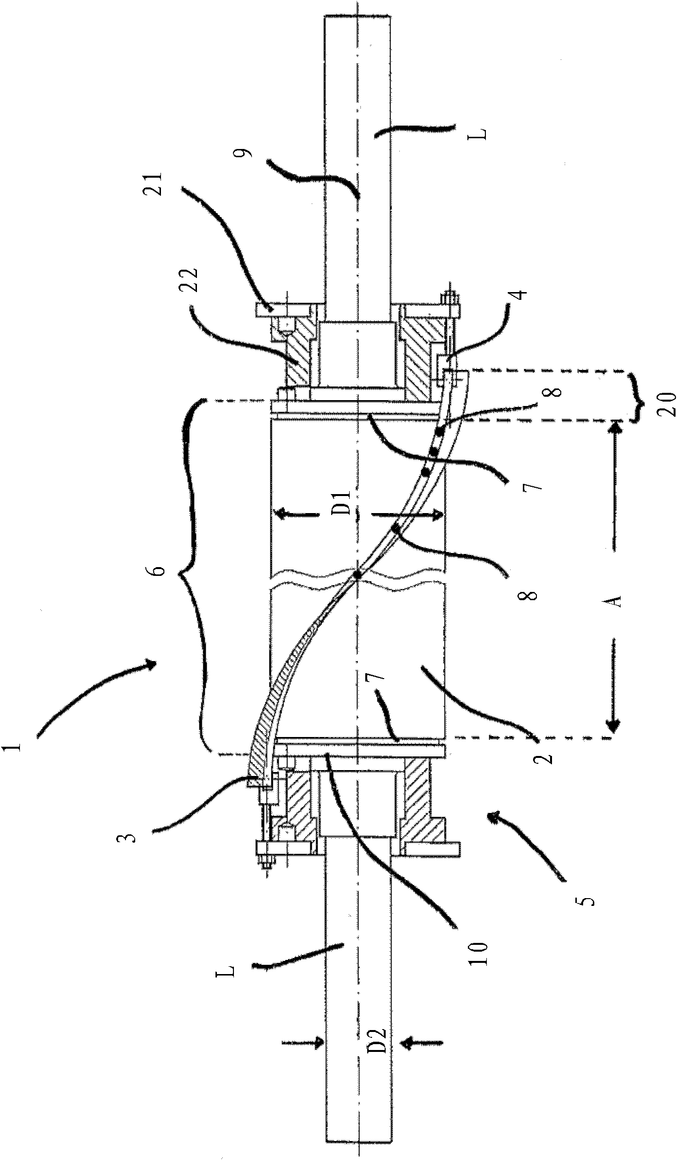
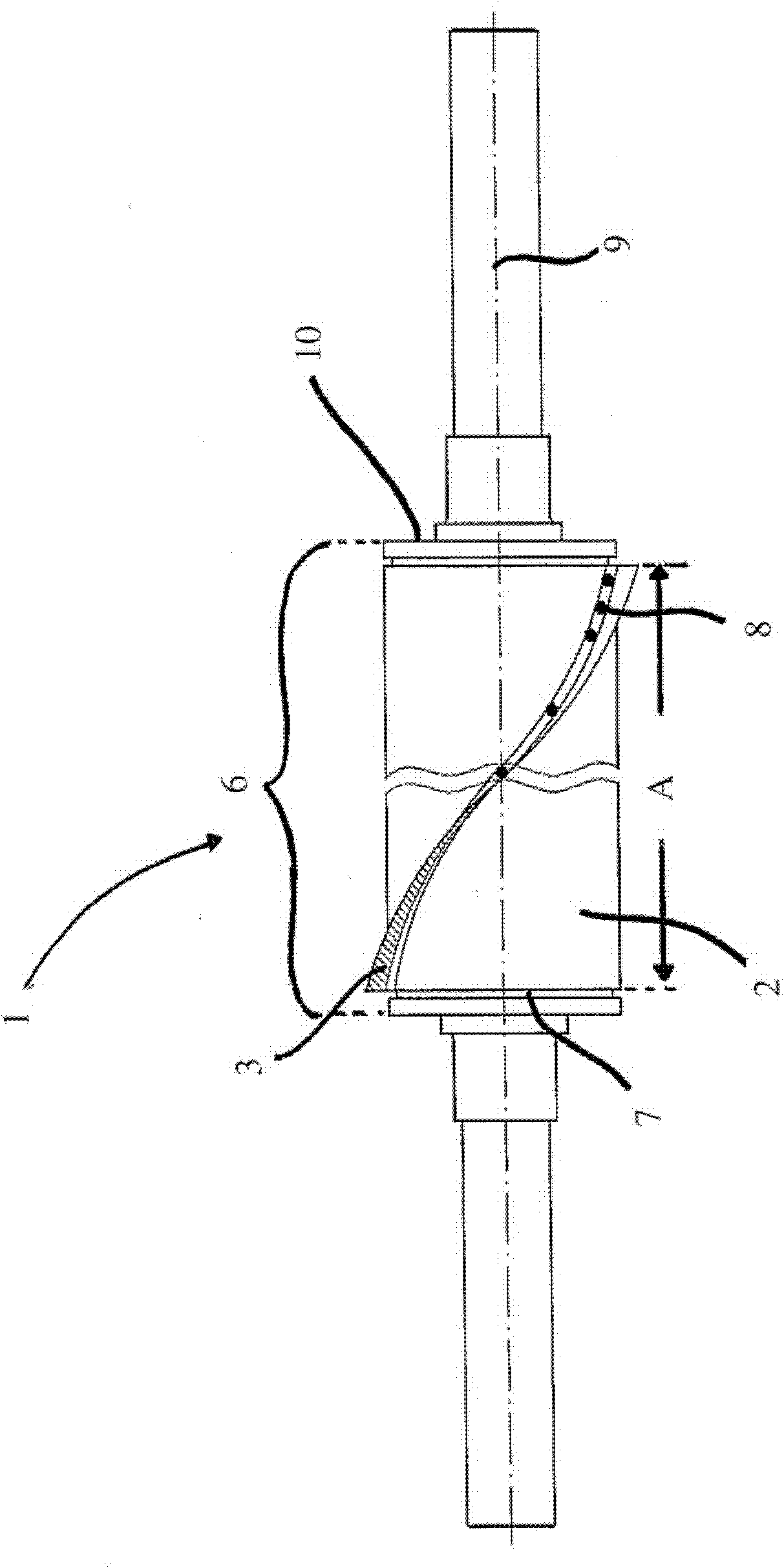
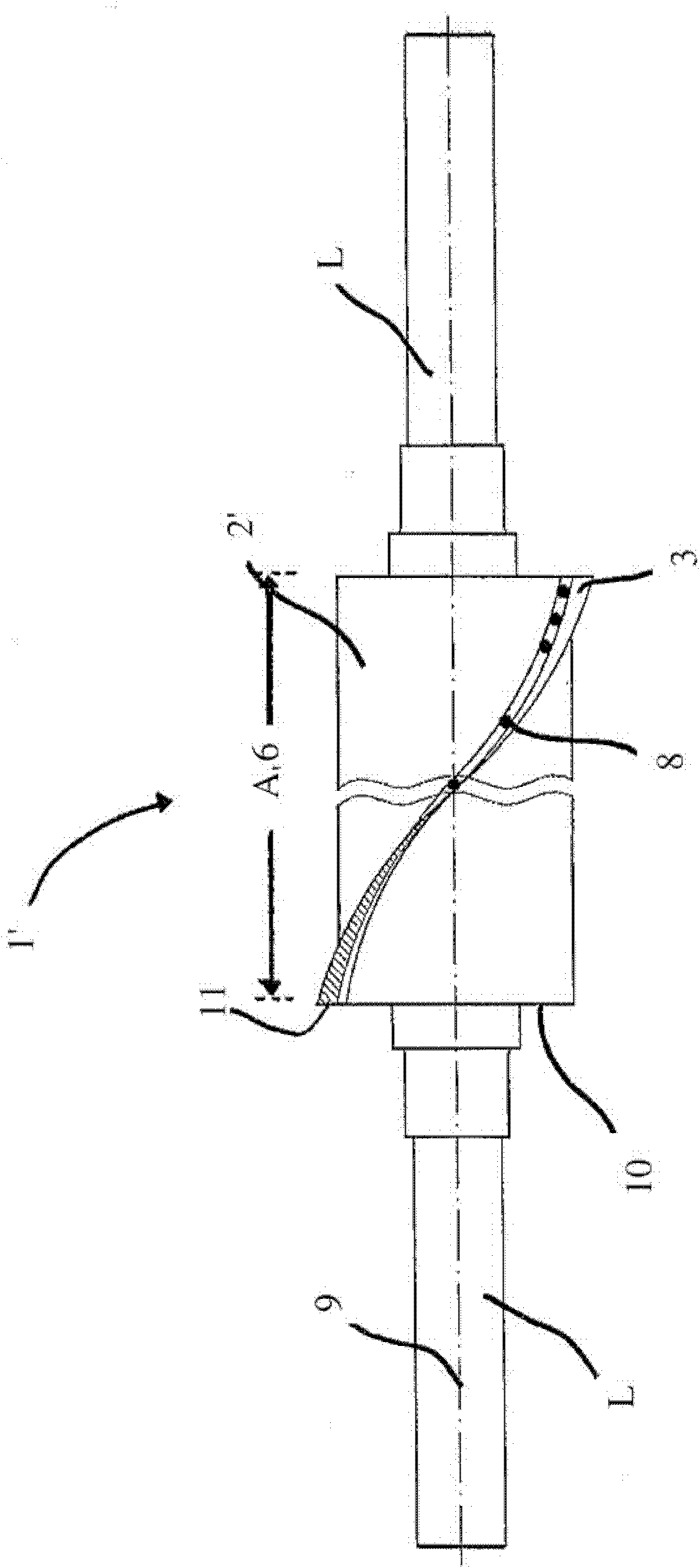
[0050] figure 1 Denotes a cutting device 1, which has a cylinder 2 and a blade 3. As already explained above, a complete set of blades is usually installed, so the steps described here are intended for the parallel implementation of several blades 3 . Of course, for some applications, only one blade 3 can be installed on the cylinder 2 as well. The method used is described here with the cutting device 1 as an example. Although it has a plurality of blades 3 in the working state, only a single blade 3 is used to illustrate the assembly process here for the sake of simplicity.

[0051] The two ends of the blade 3 are respectively provided with traction parts 4 in the tension section. The traction member 4 connects the blade 3 and the supporting body 5 respectively. The carrier body 5 shown here itself has a side plate 22 and an adapter 23 . The cylinder 2 is composed of a region 6 in which the cylinder 2 has a larger diameter D1 and two regions respectively arranged at the e...


PUM


Abstract

The invention relates to a method for assembling a helix blade on the outer surface of a cylinder body. The method comprises the following steps of making a blade having a base and a cutting edge equipped angularly relative to the base and having a blade turning back to the base equipped on the outer surface of the cylinder body through the base; and tightening the blade along the longitudinal axis of the cylinder body through at least one traction member. The traction member is respectively connected with the blade inside a tightening section in a force transmission manner. Therefore, not only the at least one traction member but also the blade ends without the traction member are respectively supported on an anchoring point. The at least traction member exerts force on one end of the blade along the helix direction. Then the blade makes the base contact face pressed and abut on the outer surface of the cylinder body. The blade is then fixed on the cylinder body through screws penetrating the base. According to the invention, the end sections (20) with traction members (4) are all cut from the blade (3); and at leat one cut end section (20) and related traction members (4) are removed.

Description

technical field [0001] The invention relates to a method for assembling a helical blade on the outer surface of a cylinder having a longitudinal axis, comprising the following process steps: [0002] a) a blade comprising a base and a cutting edge disposed at an angle relative to the base with a cutting edge facing away from the base is mounted on the outer surface of the cylinder through the base; [0003] b) The blade is tensioned in the direction of the longitudinal axis of the cylinder by means of at least one traction element, which is respectively connected to the blade in a tensioning section in a force-transmitting manner, for which reason not only the at least one traction element, but also each of the blades The end sections without traction elements are respectively supported on the anchor points, and said at least one traction element exerts a force acting in a helical direction on one end of the blade, whereby the blade presses the contact surface of the bottom ed...

Claims


Application Information

Patent Timeline
IPC IPC(8): D06H7/00D01G1/10D01H9/16
CPCB26D1/365B26D1/0006B26D7/2614
Inventor 克里斯托弗.沃尔夫
Owner 好使有限责任公司和两合公司
Why Eureka
Try Eureka