Waste water hoisting facility

A technology of waste water and coupling parts, which is applied to water supply devices, waterway systems, drainage structures, etc., and can solve problems such as invisible containers

Active Publication Date: 2012-08-22
GRUNDFOS MANAGEMENT AS
View PDF5 Cites 2 Cited by
  • Summary
  • Abstract
  • Description
  • Claims
  • Application Information

AI Technical Summary

Problems solved by technology

This is difficult because the container is usually not visible from the outside
It is especially problematic to remove the pump unit for maintenance and connect it again without dismantling the entire unit

Method used


Image

  • Waste water hoisting facility
  • Waste water hoisting facility
  • Waste water hoisting facility

Examples


Embodiment Construction

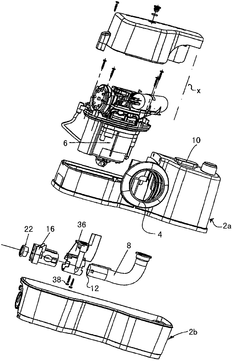
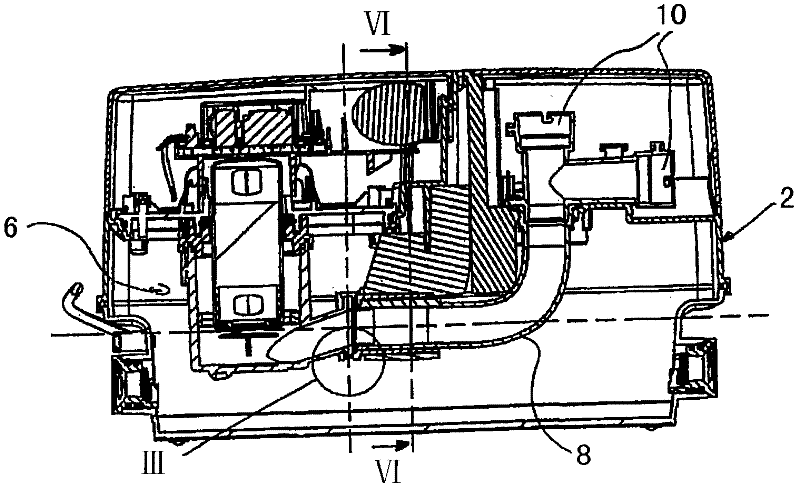
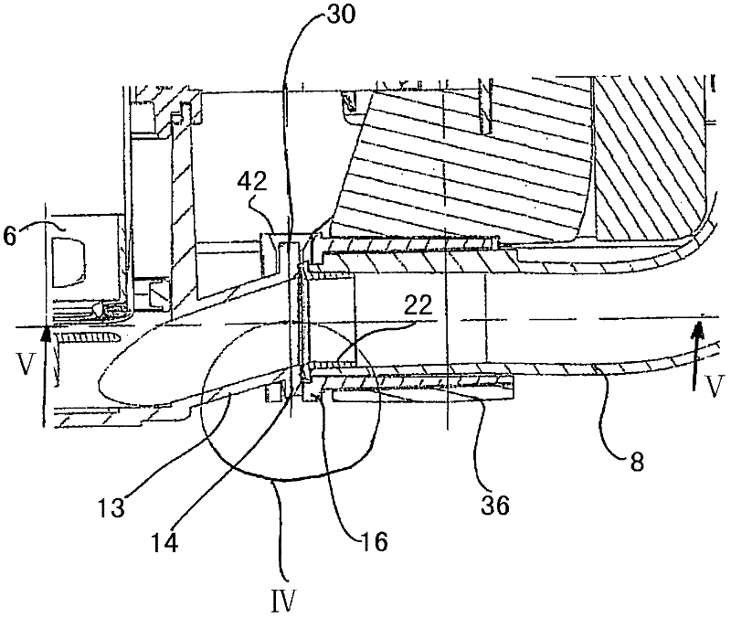
[0053] The waste water lifting device shown in this exemplary embodiment has a container 2 consisting of two container components 2a and 2b. The container assemblies 2a and 2b are preferably made of synthetic material. The container 2 has an inlet 4 for connection to, for example, a waste water line of a sanitary object such as a toilet. A pump unit 6 is arranged inside the container 2 for pumping the waste water flowing in through the inlet 4 and accumulating in the container 2 out of the container 2 to a higher liquid level. To this end, a liquid level switch (not shown here) for switching on and off the pump is provided in the container 2, which switches on the pump 6 when a predetermined water level is reached in the container 2, and when it is lowered to Second, turn off the pump 6 again when the predetermined water level is lower. On the output side, the pump is connected to a discharge line 8 arranged inside the container 2 , which leads to a discharge connection 10 ....


PUM


Abstract

The invention relates to a waste water hoisting facility, which comprises a container (2) and at least one pump unit (6) equipped inside the container. The pump unit (6) comprises a discharge sleeve pipe (13) connected with a discharge pipeline (8). The pump unit is removably inserted through an opening in a wall of the container. The discharge sleeve pipe (13) is connected with the discharge pipeline (8) through couplers (14, 16) detechable along the insertion direction (X) of the pump unit (6).

Description

technical field [0001] The invention relates to a waste water lifting device having a container and at least one pump unit arranged in the container, the pump unit having a discharge sleeve connected to a discharge line. Background technique [0002] The waste water lifting device is used to lift or pump waste water accumulated below the liquid level of the sewer pipe to above the liquid level of the sewer pipe. For this purpose, known waste water lifting devices have a container into which the waste water to be extracted flows. A pump unit is arranged on or in the container for pumping water from the container into a waste water line at a higher level. [0003] Such devices are known to have a closed container made of plastic, in which the pump unit is mounted through an opening. These containers also have all the necessary connecting lines, in particular also a discharge connection, which is connected on the outlet side to the pump unit. That is to say, within the conta...

Claims


Application Information

Patent Timeline
Patent Type & Authority Applications(China)
IPC IPC(8): E03F5/22
CPCE03F5/22F16L37/26
Inventor 拉尔夫·朔梅克卢卡·卡萨利尼亚历山德罗·拉科波尼
Owner GRUNDFOS MANAGEMENT AS
Why Eureka
Try Eureka