
Wireless charging device, power receiving device and wireless flat-panel charging system

A wireless charging and receiving device technology, applied in the direction of circuit devices, electromagnetic wave systems, battery circuit devices, etc., can solve the problems of waste of resources, increase the use of plug boards, and easy entanglement of power adapter connecting lines, etc., to achieve good versatility, Ease of use

Inactive Publication Date: 2012-08-22
SHENZHEN FEIFAN IND
View PDF4 Cites 17 Cited by
  • Summary
  • Abstract
  • Description
  • Claims
  • Application Information

AI Technical Summary

Problems solved by technology

This causes inconvenience to users
[0003] In addition, different electrical equipment usually uses different power sockets and needs to be equipped with adapters with different power plugs. Therefore, users have a lot of power adapters, which is not conducive to energy saving and environmental protection, resulting in a great waste of resources.
[0004] In addition, when multiple electrical devices need to be charged at the same time, multiple power adapters must be used at the same time, which increases the use of plug boards, and the connecting wires of the power adapters are easily entangled, causing inconvenience to users.

Method used


Image

  • Wireless charging device, power receiving device and wireless flat-panel charging system
  • Wireless charging device, power receiving device and wireless flat-panel charging system
  • Wireless charging device, power receiving device and wireless flat-panel charging system

Examples


Embodiment Construction

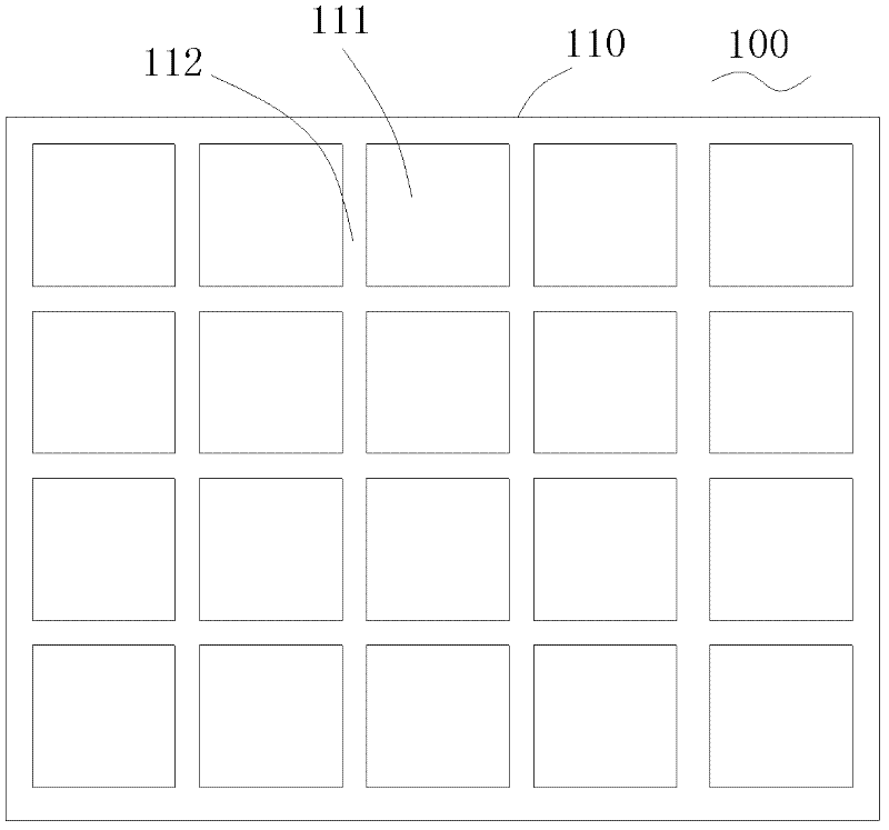
[0042] Such as figure 1 Shown is an embodiment of the wireless charging device 100 of the present invention, which can be used to provide a power supply platform for the power receiving device 150 to facilitate the use of the power receiving device 150 .

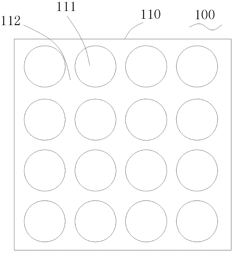
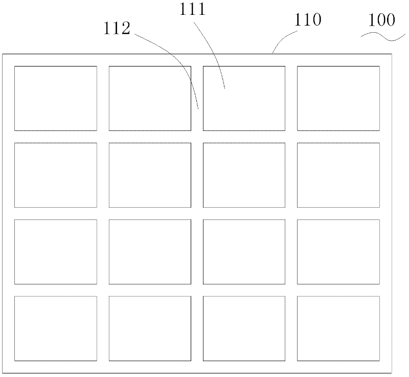
[0043] The wireless charging device 100 includes a supporting body 110 , a plurality of electrodes 111 are arranged on the surface of the supporting body 110 , and insulating gaps 112 are formed between the electrodes 111 to separate the plurality of electrodes 111 respectively. Each electrode 111 can be respectively connected to a charging power source to be connected to the power source for power supply.

[0044] As shown in the figure, the supporting body 110 of this embodiment is a flat body, and the shape and size of the flat body can be adjusted as required.

[0045] The electrodes 111 are square and arranged equidistantly on the supporting body 110 in a matrix form. It can be understood that the shape of the electro...


PUM


Abstract

The invention relates to a wireless charging device, a power receiving device and so on. The wireless charging device comprises a support main body, and at least two electrodes arranged on the surface of the support main body, wherein an insulation slit is kept between the electrodes; and each electrode is connected with a charging power supply. The power receiving device comprises at least two conductive contacts, wherein the shortest edge distance of single conductive contact is larger than the insulation slit between the electrodes of the wireless charging device; and the smallest distance between edges of the adjacent conductive contacts is larger than the largest edge distance of the single electrode. The power receiving device is disposed on the wireless charging device, and the conductive contacts of the power receiving device keeps contact with the electrodes of the wireless charging device, so that the electrodes can directly supply power to the conductive contacts, thereby providing use convenience and good universality. In addition, the power receiving device can be placed on the support main body of the wireless charging device at will to realize the electrical connection between the conductive contacts and the electrodes, thereby improving use convenience.

Description

technical field [0001] The present invention relates to a charging device, more specifically, to a wireless charging device, a power receiving device and a wireless tablet charging system. Background technique [0002] With the development of science and technology, more and more electrical equipment is used in people's life. When using such electrical equipment, it is usually directly connected to a power source through a power plug or the like to supply power to the electrical equipment, or to supply power to the battery of the electrical equipment. However, with the increase of electrical equipment, the power plug will also increase. This causes inconvenience to the user in use. [0003] In addition, different electrical devices usually use different power sockets and need to be equipped with adapters with different power plugs. Therefore, users have many power adapters, which is not conducive to energy saving and environmental protection, resulting in a great waste of ...

Claims


Application Information

Patent Timeline
Patent Type & Authority Applications(China)
IPC IPC(8): H02J7/02H02J17/00
CPCH02J7/00304H02J7/02
Inventor 麦华彬
Owner SHENZHEN FEIFAN IND
Learn More