Clutch device

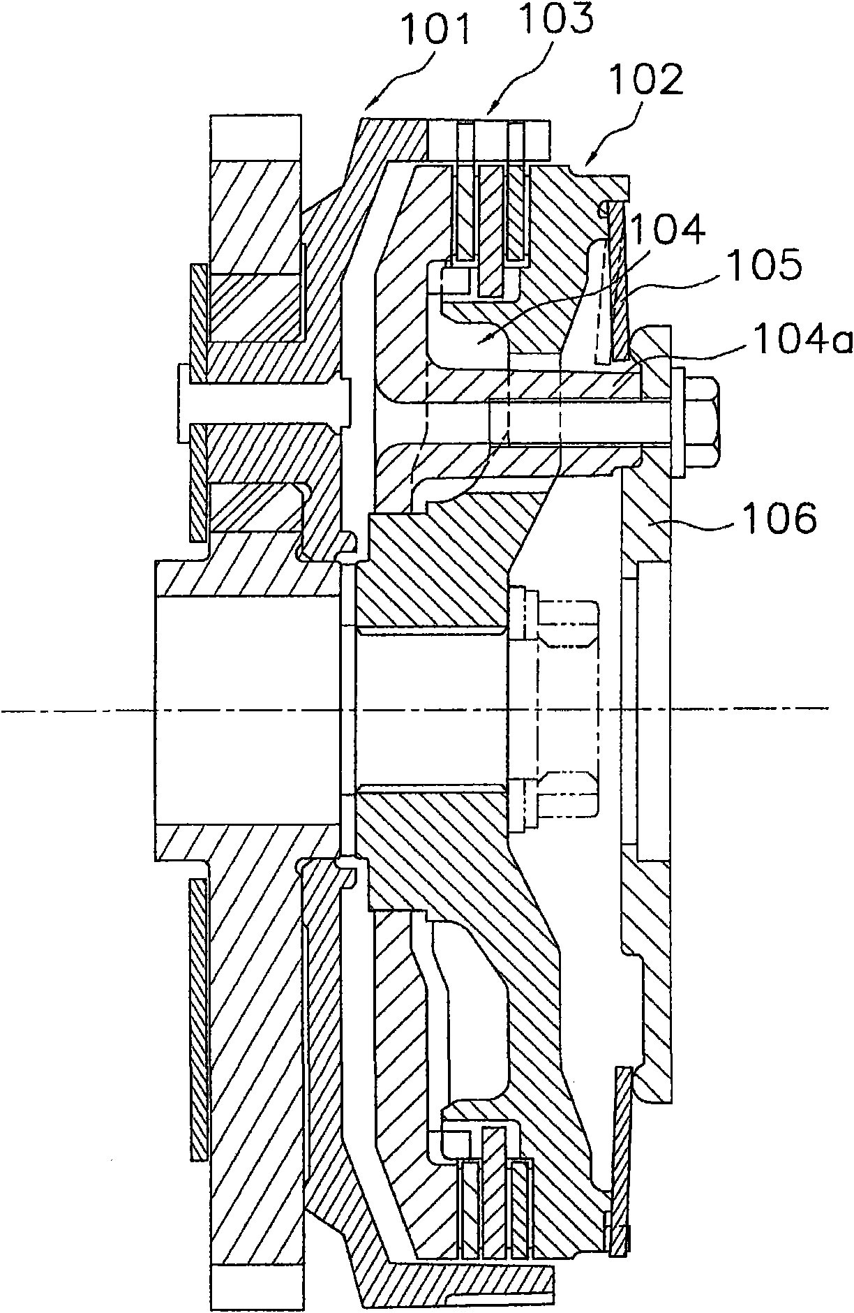
A clutch device and clutch technology, applied in the direction of clutches, friction clutches, mechanical drive clutches, etc., can solve problems such as the reduction of the pressing force of the pressing part 105

Inactive Publication Date: 2012-08-22
EXEDY CORP
View PDF5 Cites 3 Cited by
  • Summary
  • Abstract
  • Description
  • Claims
  • Application Information

AI Technical Summary

Problems solved by technology

[0008] Therefore, for example, it is conceivable to form a slit in the pressing member 105 to avoid pressing the protruding portion 104a of the rotating body 104. However, once such a slit is formed, the pressing force of the pressing member 105 will be significantly reduced.

Method used


Image

  • Clutch device
  • Clutch device
  • Clutch device

Examples


Embodiment Construction

[0038]

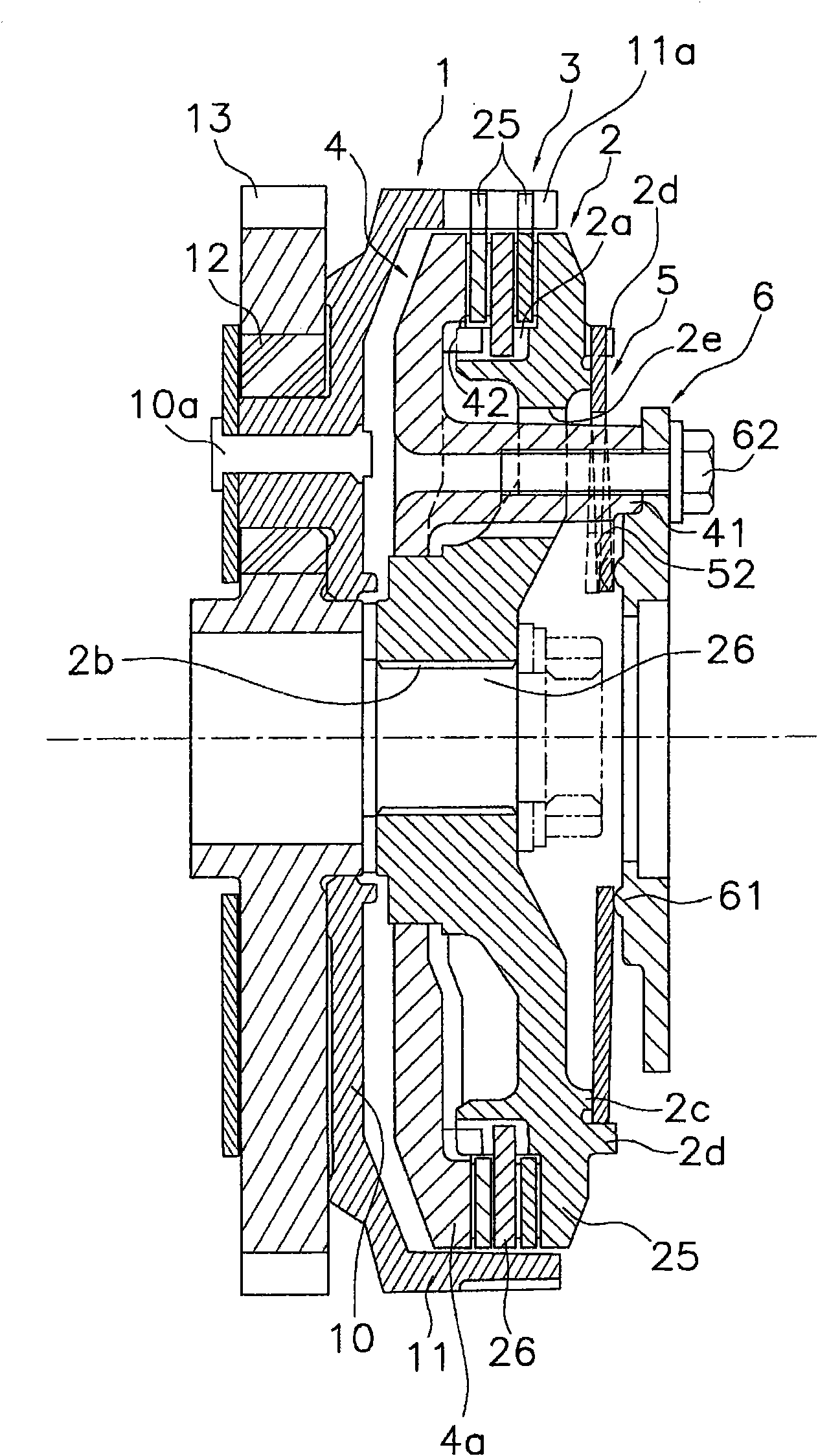
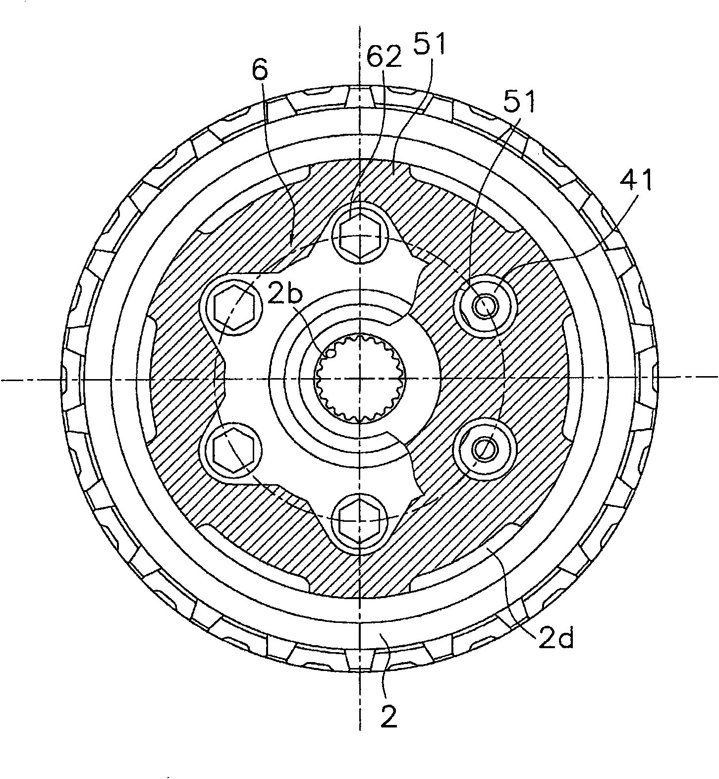
[0039] figure 1 and figure 2 The clutch device shown is a device for transmitting the power from the crankshaft of the engine to the transmission, and cutting off the power transmission by a disengagement operation. In addition, in figure 1 and figure 2 Both crankshaft and gearbox are omitted. This clutch device includes a clutch housing 1, an output side rotating body 2 (first rotating body), a clutch portion 3 for transmitting or disconnecting power between the clutch housing 1 and the output side rotating body 2, and a pressing disc member 4 ( second rotating body), diaphragm spring 5 (pressing member), and separation member 6 (disk-shaped member). In this device, the separation member 6 is moved axially inward by the separation operation ( figure 1 left in ) to cut off the power transmission.

[0040]

[0041] The clutch housing 1 is on one direction side of the axial direction ( figure 1on the right side) has an opening, and includes a disk porti...


PUM


Abstract

A clutch device that has a diaphragm spring with a reduced diameter and in which pressing pressure acting on an output-side rotation body is not reduced. The device has a clutch housing, the output-side rotation body, a clutch section, a pressure plate, the diaphragm spring, and a release member. The clutch housing is connected to an input-side member, and the output-side rotation body is connected to an output-side member. The clutch section has clutch plates for performing transmission and interruption of power between the clutch housing and the pressure plate. The pressure plate can hold the clutch plates and has projections. The diaphragm spring has through-holes through which the projections can pass. The release member is fixed to the tips of the projections, supports at its inner periphery the inner periphery of the diaphragm spring, and releases pressing force of the diaphragm spring applied to the output-side rotation body.

Description

technical field [0001] The present invention relates to a clutch device, and more particularly, to a clutch device for transmitting power from an input-side member to an output-side member and cutting off power transmission by a disengagement operation of a disengagement mechanism. Background technique [0002] Generally, in motorcycles such as two-wheeled vehicles and small motor vehicles, a multi-plate clutch device that transmits power from an engine to a transmission or cuts off power is used. This multi-plate clutch device includes a clutch housing connected to the crankshaft side of the engine, an output-side rotating body connected to the transmission side, a clutch part required to transmit and cut off power between these devices, and a clutch part for pressing the clutch part. platen. In the clutch unit, first clutch plates engaged with the clutch housing and second clutch plates engaged with the output-side rotating body are alternately arranged. [0003] Further...

Claims


Application Information

Patent Timeline
Patent Type & Authority Applications(China)
IPC IPC(8): F16D13/71
Inventor 今西义夫鹤田浩吉
Owner EXEDY CORP
Why Eureka
Try Eureka