Mounting method of piston clamping spring

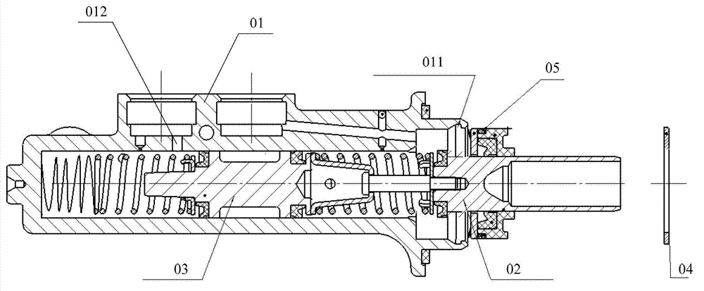
An installation method and circlip technology, used in metal processing, metal processing equipment, manufacturing tools, etc., can solve the problems of scratching, labor, and oil leakage of the cylinder block 01, and achieve the effect of avoiding scratches

Active Publication Date: 2013-01-30
LIUZHOU WULING MOTORS +1
View PDF5 Cites 1 Cited by
  • Summary
  • Abstract
  • Description
  • Claims
  • Application Information

AI Technical Summary

Problems solved by technology

[0006] However, the outer circumference of the piston body of the first piston assembly is provided with an O-ring seal 05, and when the first piston assembly is pressed into the cylinder body 01, the O-ring seal 05 is prone to contact with the cylinder body 01 under the pressing force. Scratches may cause the O-ring 05 to be scratched, which may lead to oil leakage from the piston
[0007] In addition, during the installation process, the staff needs to overcome the elastic force of the spring of the second piston assembly with one hand, which is laborious
[0008] Therefore, how to solve the problem that the O-ring is easily scratched in the prior art piston assembly process has become an important technical problem to be solved by those skilled in the art.

Method used


Image

  • Mounting method of piston clamping spring
  • Mounting method of piston clamping spring
  • Mounting method of piston clamping spring

Examples


Embodiment Construction

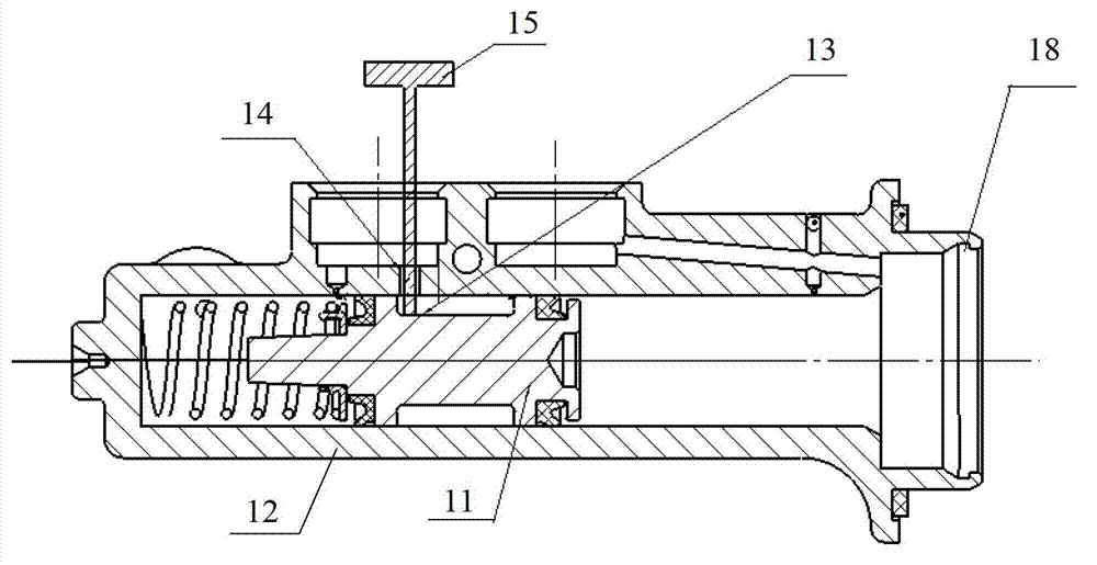
[0031] The invention provides a method for installing a piston circlip, which can avoid the problem that the O-ring is scratched.

[0032] The technical solutions in the embodiments of the present invention will be clearly and completely described below with reference to the accompanying drawings in the embodiments of the present invention. Obviously, the described embodiments are only a part of the embodiments of the present invention, but not all of the embodiments. Based on the embodiments of the present invention, all other embodiments obtained by those of ordinary skill in the art without creative efforts shall fall within the protection scope of the present invention.

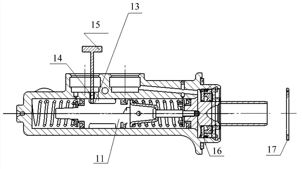
[0033] Please refer to figure 2 and image 3 , figure 2 It is a schematic diagram of the first state in the piston assembly process in the specific embodiment of the present invention; image 3 It is a schematic diagram of the second state during the assembly process of the piston in the specific emb...


PUM


Abstract

The invention discloses a mounting method of a piston clamping spring, comprising the following steps of: S01, putting a second piston assembly into a cylinder body; S02, pressing the second piston assembly to enable a spring of the second piston assembly to be at a compressed state and corresponding a groove on the periphery of a piston body of the second piston assembly to an oil inlet of the cylinder body; S03, inserting a limiting rod into the oil inlet of the cylinder body and stretching the end part of the limiting rod into the groove on the periphery of the piston body of the second piston assembly so as to release pressing acting force on the second piston assembly; S04, arranging a first piston assembly into the cylinder body; and S05, arranging the clamping spring into a clamping spring groove in the cylinder body and pulling the limiting rod out of the oil inlet of the cylinder body. According to the mounting method of the piston clamping spring, the problem of scraping an O-shaped sealing ring can be avoided.

Description

technical field [0001] The invention relates to the technical field of piston assembly, and more specifically, relates to a method for installing a piston circlip. Background technique [0002] The piston includes a piston cylinder and a piston assembly disposed in the piston cylinder. There are many types of pistons. The following content will briefly introduce a piston in the prior art with reference to the accompanying drawings. [0003] like figure 1 shown, figure 1 It is a schematic diagram of a piston assembly structure in the prior art. [0004] The piston in the prior art includes a cylinder body 01 and a first piston assembly 02 and a second piston assembly 03 arranged in the cylinder body 01 , and an oil inlet 012 is provided at the rear of the cylinder body 01 . In the assembly process of the piston, firstly, the second piston assembly 03 needs to be installed into the cylinder body 01 through the opening of the cylinder body 01, then the first piston assembly ...

Claims


Application Information

Patent Timeline
Patent Type & Authority Applications(China)
IPC IPC(8): B23P19/027
Inventor 潘操李丽石丽玲龙理燕覃云
Owner LIUZHOU WULING MOTORS
Why Eureka
Try Eureka