Seat slide device

a seat and slide technology, applied in the field of seat slide devices, can solve the problems of increasing the number of parts, difficult to insert the two lock portions into the lock groove, and the assemblability of the seat slide devices is poor, so as to reduce the amount of deformation of the lock member and improve the lock strength

Active Publication Date: 2019-09-19
TF METAL CO LTD
View PDF5 Cites 1 Cited by
  • Summary
  • Abstract
  • Description
  • Claims
  • Application Information

AI Technical Summary

Benefits of technology

[0013]According to the aforementioned configuration, when the seat slide device receives impact load in the vehicle front-rear direction, the left and right lock teeth closest to the swing fulcrum portion come into contact with the lock grooves before the other lock teeth farther away from the swing fulcrum portion do. In this case, c

Problems solved by technology

Since the distal end of the operation handle is passed through the two holes in the lock member in this insertion, the aforementioned seat slide device has very poor assemblability.
Accordingly, a biasing portion to bias the lock member in the lock direction and a biasing portion to bias the operation handle upwar

Method used


Image

  • Seat slide device
  • Seat slide device
  • Seat slide device

Examples


first embodiment

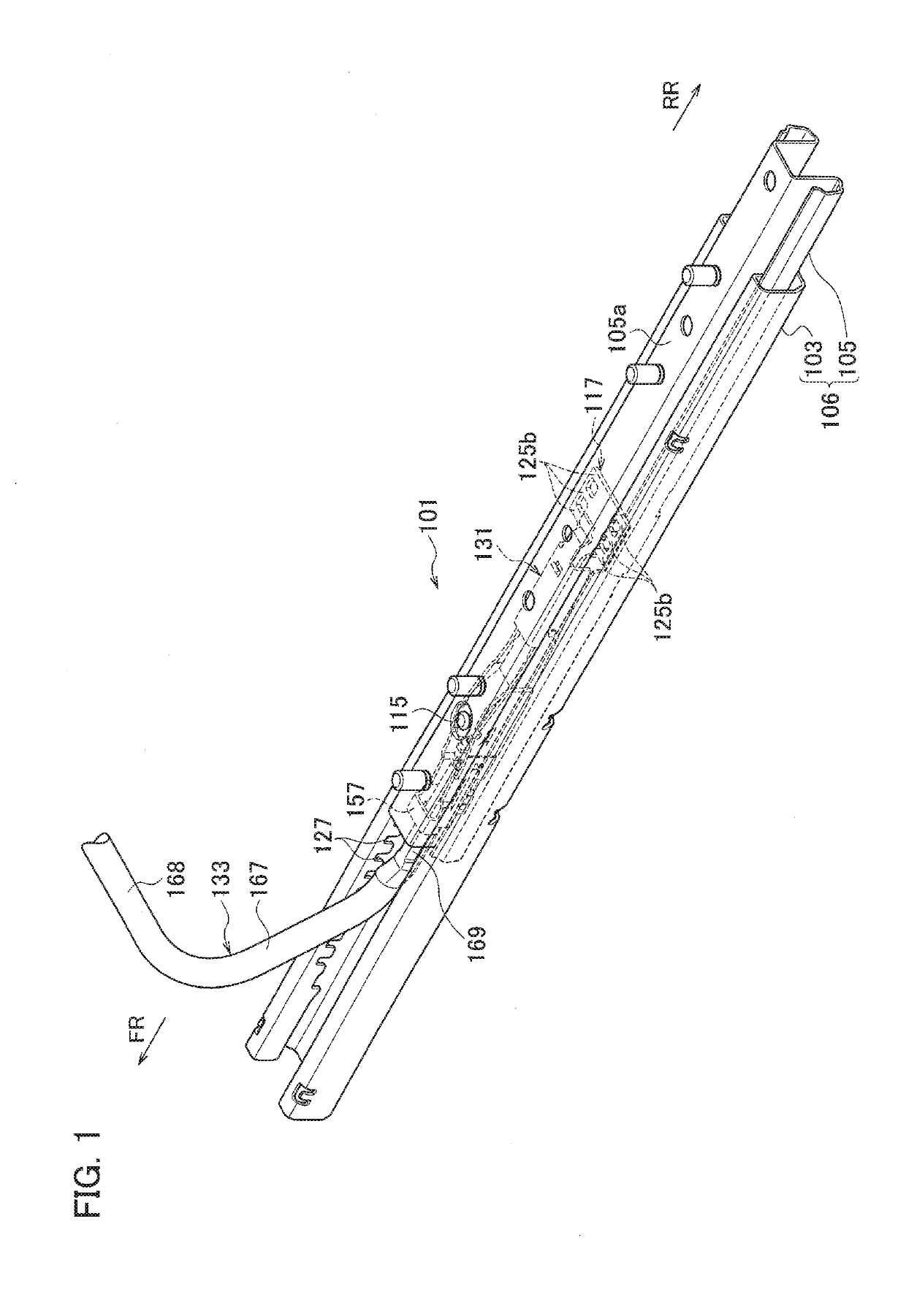
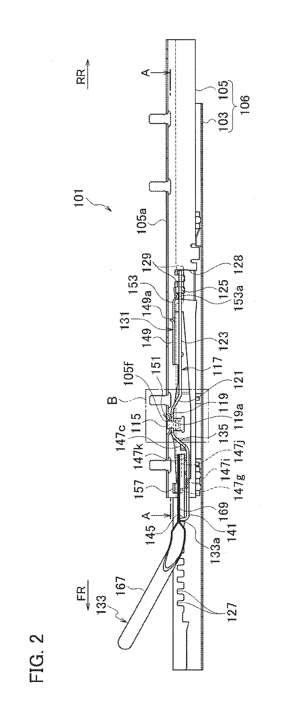
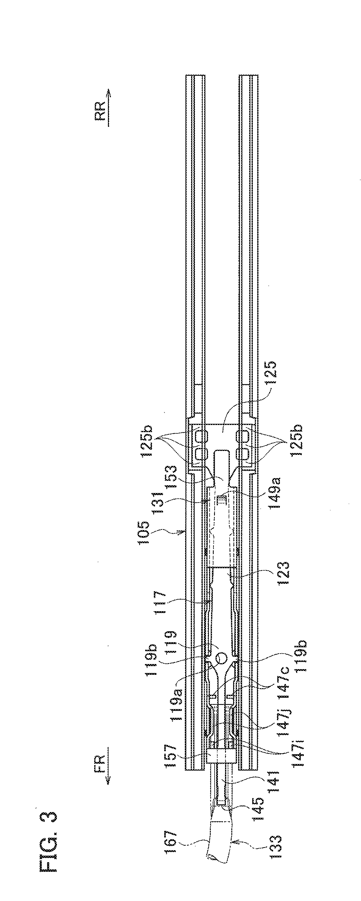
[0053]A seat slide device 10 according to a first embodiment of the present invention illustrated in FIGS. 1 to 4 is a manual seat slide device in which the position of a vehicle seat n a front-rear direction is adjusted manually. The seat slide device 101 includes a lower rail 103 installed on a floor surface of a vehicle and extending in a vehicle front-rear direction (hereafter, simply referred to as front-rear direction in some cases) and an upper rail 105 installed on a back surface of a seating portion (not illustrated) of a seat and assembled to be movable inside the lower rail 103 relative thereto in a longitudinal direction of the lower rail 103. The lower rail 103 and the upper rail 105 form a rail body 106 and paired left and right rail bodies (a pair of rail bodies) 106 are provided. In FIGS. 2 and 3, illustration of the lower rail 103 is omitted. Note that, in the following description (including second and third embodiments), “front” is the vehicle front FR side which ...

second embodiment

[0133]FIG. 19 is a side cross-sectional view of a seat slide device 101A according to a second embodiment which corresponds to FIG. 2. The second embodiment is different from the first embodiment in some portions of the release lever 131 and some portions of the operation handle 133. The lower rail 103 and the upper rail 105 in the second embodiment are the same as those in the first embodiment.

[0134]The lock member 117 in the second embodiment has substantially the same basic shape as that in the first embodiment. However, as illustrated in FIGS. 19 and 21A, a tilted portion 141a is formed in a portion of the front elastic deformation portion 141 on the front end claw 145 side. A portion on the front tilted portion 135 side of the tilted portion 141a is a flat surface 141b. The tilted portion 141a is tilted such that a portion of the tilted portion 141a on the front end claw 145 side is located above a portion of the tilted portion 141a on the flat surface 141b side.

[0135]Next, a r...

third embodiment

[0179]A third embodiment of the present invention is described below with reference to FIGS. 1 to 18 and FIGS. 31 and 32. Since FIGS. 1 to 18 are the same as in the first embodiment, description thereof is omitted below and the description in the first embodiment is incorporated.

[0180]FIG. 31 is a plan view illustrating a state where the lock teeth 125b of the lock member 117 are in engagement with the respective lock grooves 127. FIG. 32 is a side view of the engagement state in FIG. 31 as viewed from the inner side of the right upper-rail side wall 105b of the upper rail 105 and illustration of the lower-rail bottom wall 103a of the lower rail 103 is omitted. Note that, in FIGS. 31 and 32, the three lock teeth 125b on the right side (upper side in FIG. 31) are referred to as lock teeth 125b1, 125b2, 125b3 from the front side (left side in FIG. 31) and the three lock teeth 125b on the left side (lower side in FIG. 31) are referred to as lock teeth 125b4, 125b5, 125b6 from the front...


PUM


Abstract

A release lever includes: a release pressing portion pressing a portion around a lock portion of a plate spring to release an engagement of the lock portion with a locked portion; an operation portion located in a front side of the release lever and operated by a lock release operation of an operation handle; and a swing fulcrum portion provided between the release pressing portion and the operation portion. The plate spring integrally includes: a base including the swing fulcrum portion and fixed to an upper rail; a rear biasing portion located behind the base in a vehicle front-rear direction and biasing the lock portion in a lock direction; and a front biasing portion located in front of the base in the vehicle front-rear direction and biasing the operation handle upward. The front biasing portion has a biasing force smaller than that of the rear biasing portion.

Description

CROSS REFERENCE TO RELATED APPLICATION[0001]This application is based upon and claims the benefit of priority from the prior Japanese Patent Application Nos. 2018-160224 filed on Aug. 29, 2017, 2018-049481 filed on Mar. 16, 2018 and 2018-049494 filed on Mar. 16, 2018, the entire contents of which are incorporated herein by reference.BACKGROUND1. Technical Field[0002]The disclosure relates to a seat slide device provided in a vehicle.2. Related Art[0003]In a seat slide device for a vehicle, an upper rail fixed to a seat is provided to be movable by sliding on a lower rail fixed to a vehicle body, and lock teeth (lock portion) of a lock member attached to the upper rail engage with lock grooves in the lower rail to lock the seat. In a lock member described in Japanese Patent Application Publication No. Hei 9-104266, an opening is provided in a flange bent downward in front of a fixation portion to an upper rail, an operation handle is inserted into this opening from the front side, an...

Claims


Application Information

Patent Timeline
IPC IPC(8): B60N2/08B60N2/07
CPCB60N2/0705B60N2/085B60N2/08B60N2/0722B60N2/0818B60N2/0875B60N2/0887
Inventor TAMAKI, KAZUKIKURODA, HIROTSUGUMASE, FUMISATOKURODA, SHUNSUKE
Owner TF METAL CO LTD
Why Eureka
Try Eureka