Lane departure warning apparatus and system

A technology of lane departure and warning device, which is applied to the traffic control system, signal device, closed-circuit television system of road vehicles, etc., can solve the problem of false alarm and other problems, and achieve the effect of preventing false alarm and no alarm, and preventing lane departure.

Active Publication Date: 2012-08-29
CLARION CO LTD
View PDF10 Cites 25 Cited by
  • Summary
  • Abstract
  • Description
  • Claims
  • Application Information

AI Technical Summary

Problems solved by technology

Then, when the vehicle reaches point C, it will deviate from the dotted line 1303, so even if it goes straight on the main line, an alarm will be generated, which becomes a false alarm

Method used


Image

  • Lane departure warning apparatus and system
  • Lane departure warning apparatus and system
  • Lane departure warning apparatus and system

Examples


no. 1 Embodiment approach

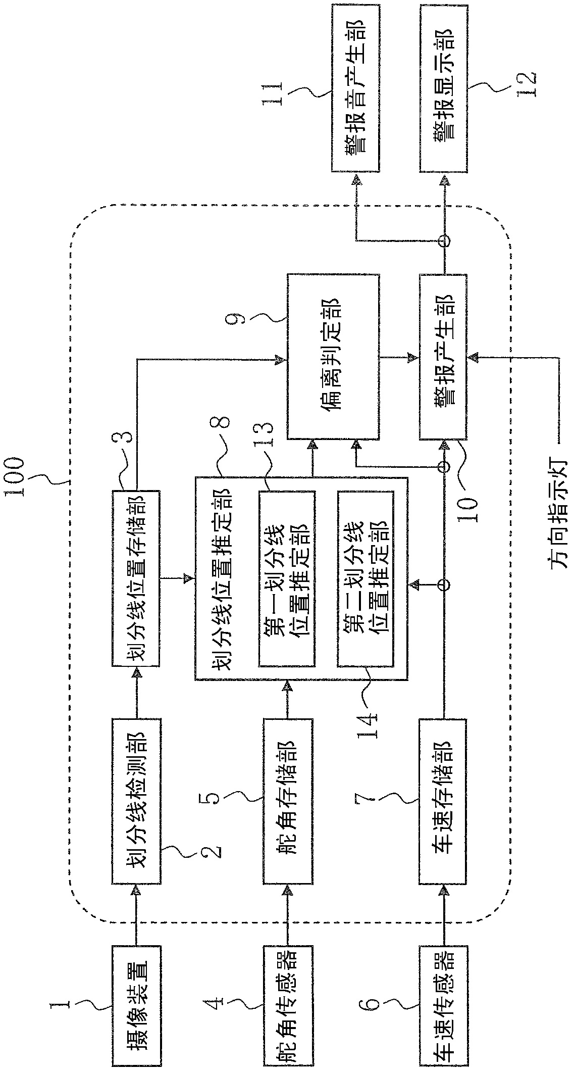
[0034] figure 1 It is a schematic diagram of the lane departure warning system in the first embodiment.

[0035] The lane departure warning system includes a lane departure warning device 100 , an imaging device 1 , a steering angle sensor 4 , a vehicle speed sensor 6 , a warning sound generator 11 , and a warning display unit 12 .

[0036] First, the configuration and processing contents of the lane departure warning device 100 will be described.

[0037] The lane departure warning device 100 is composed of a dividing line detection unit 2, a dividing line position storage unit 3, a steering angle storage unit 5, a vehicle speed storage unit 7, a dividing line position estimation unit 8, a first dividing line position estimation unit 13, a second dividing line The position estimating unit 14 , the departure determining unit 9 , and the warning generating unit 10 are configured, and are programmed by a computer (not shown) of the lane departure warning device 100 to be repea...

no. 2 Embodiment approach

[0101] Figure 9 It is a schematic diagram of the lane departure warning device 100 of the second embodiment.

[0102] Figure 9 shows the structure of the first embodiment ( figure 1 ) in which the first dividing line position estimating unit 13 and the second dividing line position estimating unit 14 are removed.

[0103] Next, the overall processing content of the lane departure warning device according to the second embodiment will be described.

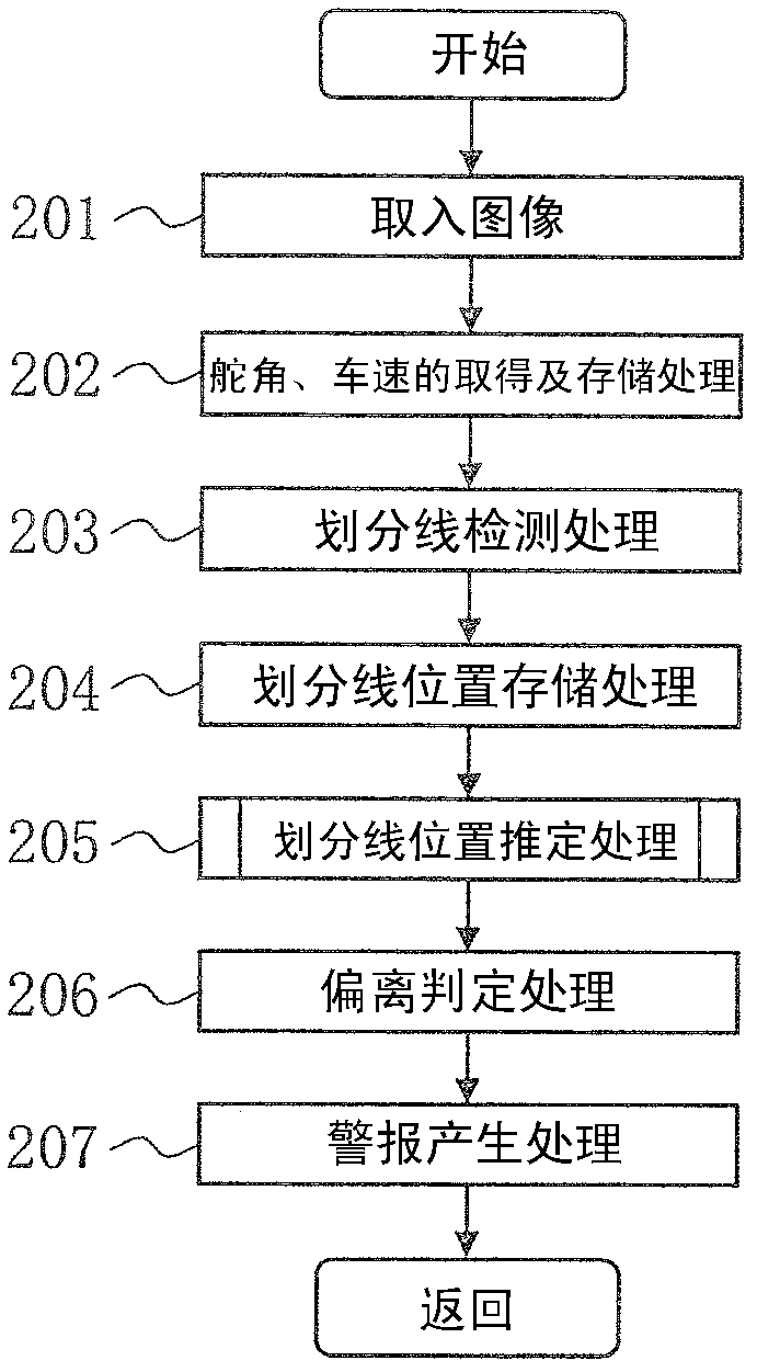
[0104] A flow chart showing the processing contents of the lane departure warning device 100 and figure 2 The flow charts shown are the same, but the demarcation line position estimation processing in processing 205 is different, so using Figure 10 The flow chart is described.

[0105] First, in processing 1001, it is determined whether or not a dividing line is currently being estimated based on the status of the dividing line estimating flag. When the dividing line is being estimated (the dividing line estimating flag ...

no. 3 Embodiment approach

[0143] Figure 16 It is a schematic diagram of the lane departure warning device 100 of the third embodiment.

[0144] Figure 16 shows the structure of the second embodiment ( Figure 9 ) in which the navigator 20 and the road information acquisition unit 21 are added.

[0145] The navigator 20 is a device that calculates the position of the own vehicle on a map represented by a car navigation system. Since the method of calculating the position of the own vehicle is known, description thereof will be omitted. When there is a special road shape (branch road, merge road, toll gate, etc.) on the planned driving route near the own vehicle, the navigator 20 outputs information such as the type of road to the lane departure warning device 100 using a communication means such as an in-vehicle LAN. .

[0146] The road information acquiring unit 21 acquires information input from the navigator 20 using a communication means such as an in-vehicle LAN. As the content of specific i...


PUM


Abstract

The invention provides a lane departure warning apparatus and a system. The lane departure warning apparatus is capable of preventing false warnings and absence of a warning regarding lane departure which is attributed to special road geometries such as junctions and tollgates. The lane departure warning apparatus for outputting a warning signal upon determining departure of a vehicle from a lane, performing the steps of: when one dividing line in a vehicle width direction of the vehicle is non-detected, estimating a position of the one dividing line based on a position of the other dividing line as a first estimation dividing line; estimating a position of the non-detected one dividing line based on a position of the one dividing line prior to non-detection as a second estimation dividing line; and comparing the first estimation dividing line with the second estimation dividing line to determine lane departure. Accordingly, the lane departure warning apparatus can avoid false alarm and no alarm of lane departure caused by special road shapes such as forks, toll stations, etc.

Description

technical field [0001] The present invention relates to a lane departure warning device for determining lane departure of a vehicle. Background technique [0002] About photographing the surroundings of the vehicle with an on-board camera, and recognizing objects (vehicles, pedestrians, etc.) or road markings and signs (road paint such as dividing lines, signs such as stops, etc.) in the captured images technology, various schemes have been proposed. For example, if an on-board camera can recognize the dividing line formed by applying paint on the road and obtain the position of the vehicle in the lane, it will be possible to issue a warning to the driver when the vehicle deviates from the lane, or control steering or braking to suppress the departure. [0003] As such a system that issues an alert when the vehicle deviates from the lane, there is a Lane Departure Warning System (LDWS: Lane Departure Warning Systems) standardized by JIS D 0804 of JIS (Japanese Industrial St...

Claims


Application Information

Patent Timeline
Patent Type & Authority Applications(China)
IPC IPC(8): B60Q9/00H04N7/18
CPCG08G1/167B60W30/12B60W2420/42B60Q9/008G06V20/588
Inventor 今井正人冈田隆坂田雅男
Owner CLARION CO LTD
Why Eureka
Try Eureka