Dual-gear oil pump

A duplex gear and oil pump technology, applied in the direction of pumps, pump components, rotary piston pumps, etc., can solve the problem of increasing the radial force, coaxiality and position accuracy of the front driving gear and the rear driving gear, and the difficulty in positioning Problems such as the large shape of each part of the pin hole can reduce the radial force, improve the volumetric efficiency and service life, and achieve the effect of compact shape and size

Inactive Publication Date: 2012-08-29
HEFEI CHANGYUAN HYDRAULICS
View PDF5 Cites 1 Cited by
  • Summary
  • Abstract
  • Description
  • Claims
  • Application Information

AI Technical Summary

Problems solved by technology

[0003] In the prior art, the parts are positioned and connected by two positioning pins, such as Figure 9 As shown, the existing problem is that when the positioning pin holes are processed on the two ends of the front pump body and the rear pump body, it is difficult to ensure the coaxiality and position accuracy, so it is difficult to ensure that the gear holes on the front pump body are consistent with those on the front cover. The position accuracy of the main shaft hole and the gear hole on the rear pump body and the main shaft hole on the connecting plate increases the radial force of the front driving gear and the rear driving gear, reduces the service life of the gear oil pump, and reduces the product performance , at the same time, the shape of each part is large for processing two positioning pin holes, which increases the weight and cost
[0005] In the existing technology, the oil inlet and outlet ports are generally set on the pump body, and the hydraulic oil flows directly into the pump body along the diameter direction of the gear, causing a great impact on the gear set and affecting the service life of the gear oil pump.

Method used


Image

  • Dual-gear oil pump
  • Dual-gear oil pump
  • Dual-gear oil pump

Examples


Embodiment Construction

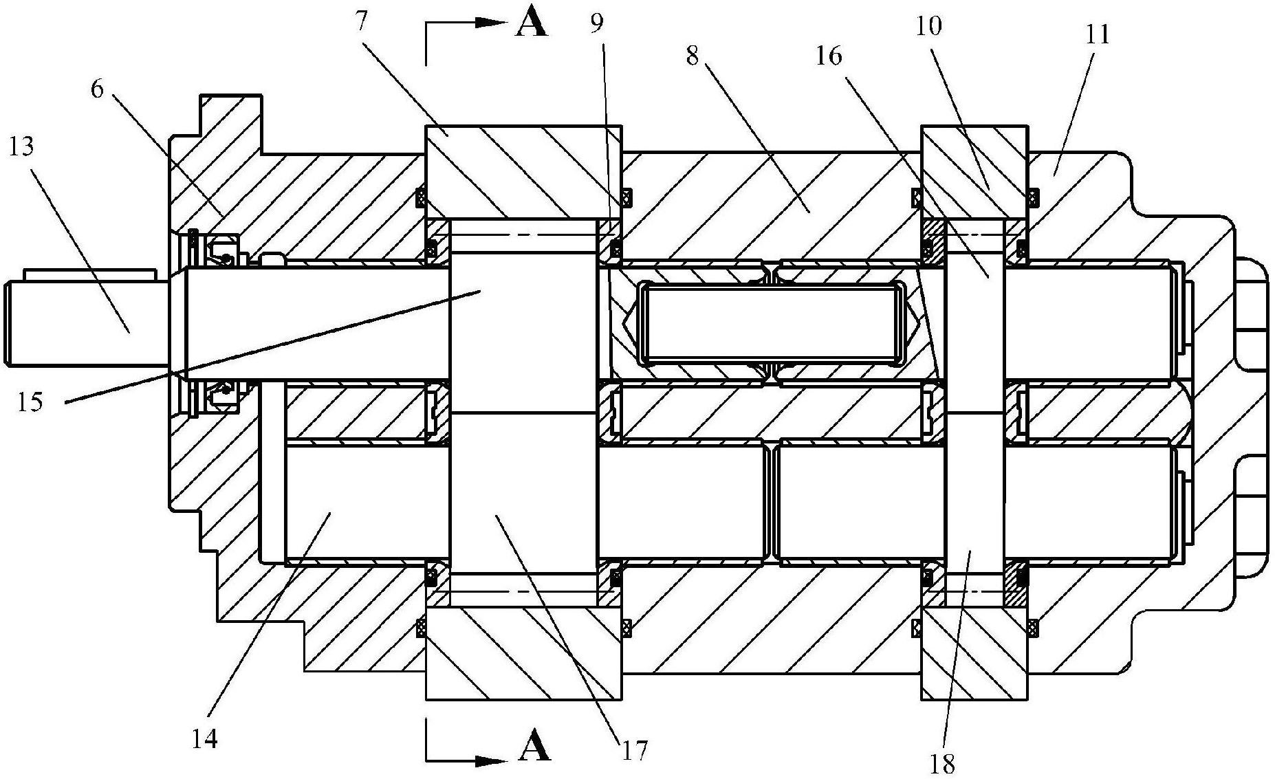
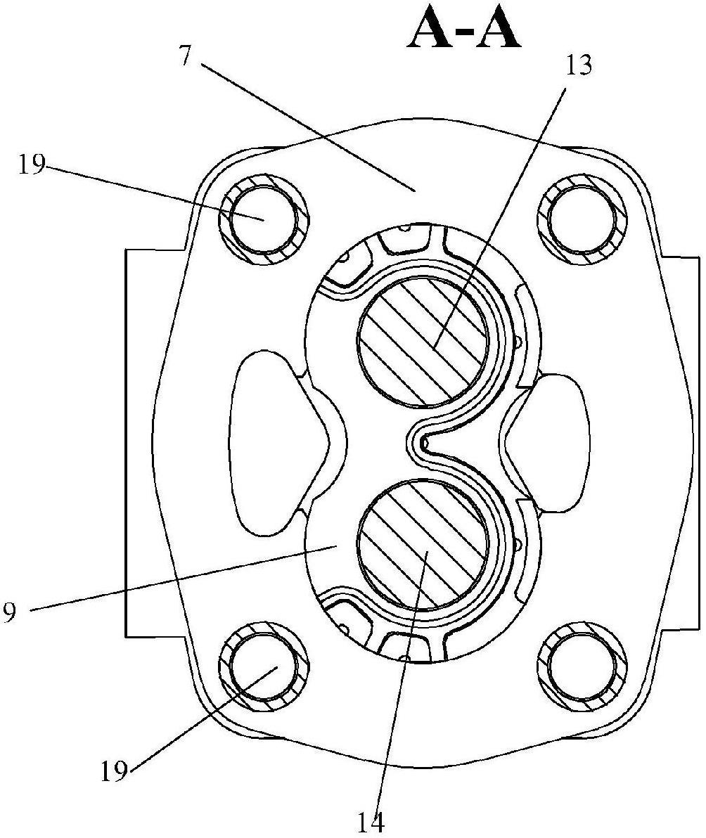
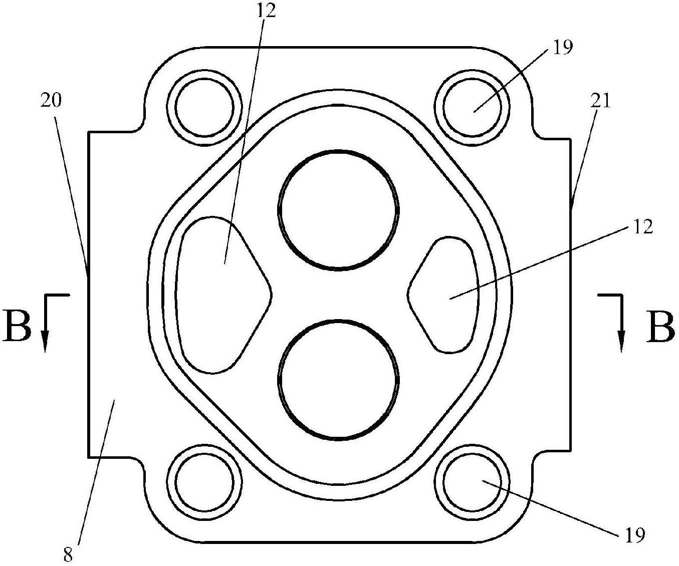
[0030] see attached picture figure 1 ~ attached Figure 8 , a double gear oil pump, including an oil pump body, a gear shaft and a gear; the gear shaft is arranged in the cavity of the oil pump body, and the gear is sleeved on the gear shaft; the oil pump body includes a front cover 6, Front pump body 7, connecting plate 8, side plate 9, rear pump body 10 and rear cover 11, the front cover 6, front pump body 7, connecting plate 8, rear pump body 10 and rear cover 11 are in order from left to right Set, the side plate 9 is located in the inner cavity of the front pump body 7 and the rear pump body 10; the gear shaft includes a driving gear shaft 13 and a driven gear shaft 14; the gear includes a front driving gear 15, a rear driving gear Gear 16, front driven gear 17 and rear driven gear 18; said front driving gear 15 and front driven gear 17 are meshed, and two side plates 9 are respectively positioned at said front driving gear 15 and front driven gear 17 Both sides; the r...


PUM


Abstract

The invention discloses a dual-gear oil pump, wherein gear shafts are arranged in a cavity of an oil pump body, and gear sleeves are sleeved on the gear shafts; the oil pump body comprises a front cover, a front pump body, a connection plate, side plates, a rear pump body and a rear cover, and the side plates are positioned in the cavities of the front pump body and the rear pump body; the gear shafts respectively comprise a drive gear shaft and a driven gear shaft; gears respectively comprise a front drive gear, a rear drive gear, a front driven gear and a rear driven gear; the front drive gears are meshed with the front driven gears, and the two side plates are respectively positioned at the two sides of the front drive gears and the front driven gears; and the rear drive gears are meshed with the rear driven gears, and the other two sides plates are respectively positioned at the two sides of the rear drive gears and the rear driven gears. The dual-gear oil pump has the advantages that the position precisions of gear holes and spindle holes can be ensured, the stress balance of the gears is realized, the bearing and shock-resistance capabilities of the gear oil pump are improved, the starting torque of the gear oil pump and heat which is produced by the friction among between the gears and the side plates are reduced and the like.

Description

technical field [0001] The invention relates to a double gear oil pump. Background technique [0002] According to the relevant national standards of the mining industry, gear oil pumps used in underground operations are not allowed to be made of aluminum alloy materials, so as to prevent mine accidents caused by the inevitable aluminum and magnesium dust generated when the gear oil pump is working. In the existing technology, duplex Gear oil pump such as Figure 9 The front and rear covers, connecting plates and pump body shown are generally made of aluminum alloy, which cannot meet the explosion-proof requirements of the mining industry. [0003] In the prior art, the parts are positioned and connected by two positioning pins, such as Figure 9 As shown, the existing problem is that when the positioning pin holes are processed on the two ends of the front pump body and the rear pump body, it is difficult to ensure the coaxiality and position accuracy, so it is difficult to...

Claims


Application Information

Patent Timeline
Patent Type & Authority Applications(China)
IPC IPC(8): F04C2/18F04C15/00
Inventor 陈文辉邓玉孙小平郑鹏飞
Owner HEFEI CHANGYUAN HYDRAULICS
Why Eureka
Try Eureka