
Method for eliminating influence of vibration over measurement of incremental optical encoder

An optical encoder and incremental technology, which is applied in the direction of measuring devices, instruments, and conversion sensor output, etc., can solve the problems of poor shock resistance of incremental optical encoders, achieve great application value, expand the scope of use, and relax required effect

Inactive Publication Date: 2014-07-02
XI'AN INST OF OPTICS & FINE MECHANICS - CHINESE ACAD OF SCI
View PDF3 Cites 0 Cited by
  • Summary
  • Abstract
  • Description
  • Claims
  • Application Information

AI Technical Summary

Problems solved by technology

[0006] The present invention aims to provide a method for eliminating the influence of vibration on the measurement of incremental optical encoders, so as to solve the technical problem of poor vibration resistance of incremental optical encoders in the prior art

Method used


Image

  • Method for eliminating influence of vibration over measurement of incremental optical encoder
  • Method for eliminating influence of vibration over measurement of incremental optical encoder
  • Method for eliminating influence of vibration over measurement of incremental optical encoder

Examples


Embodiment Construction

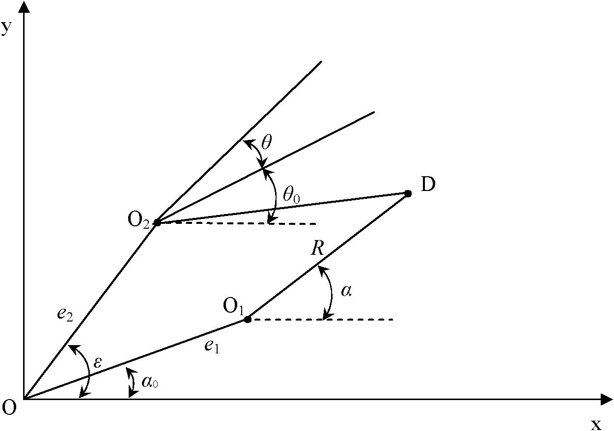
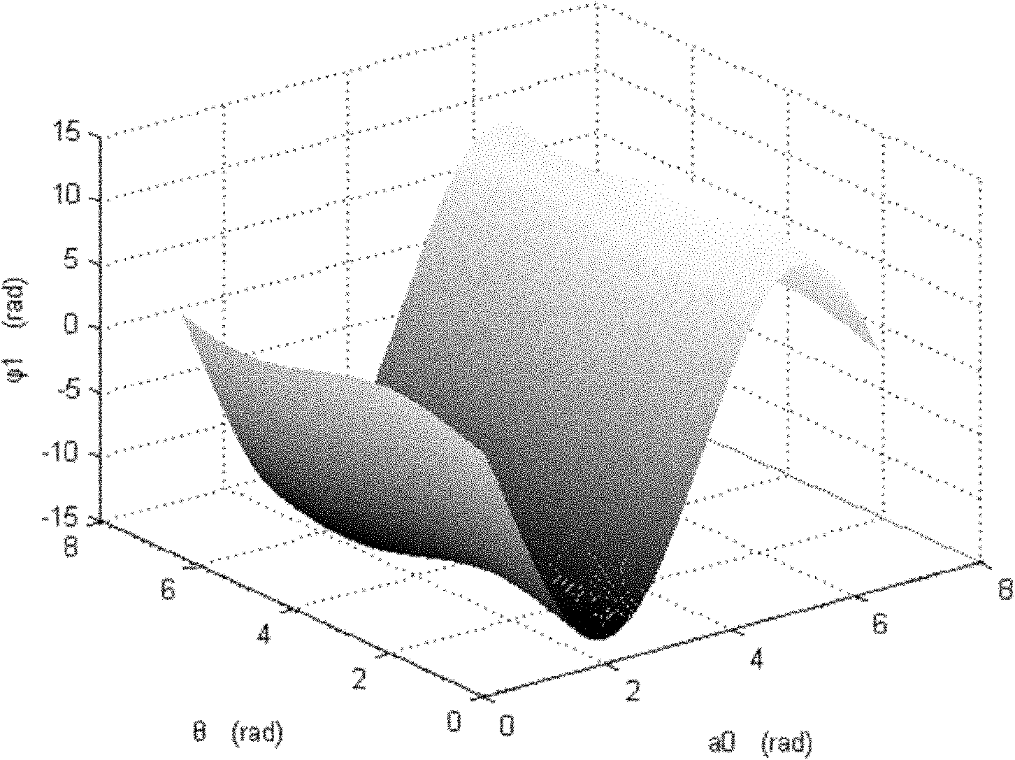
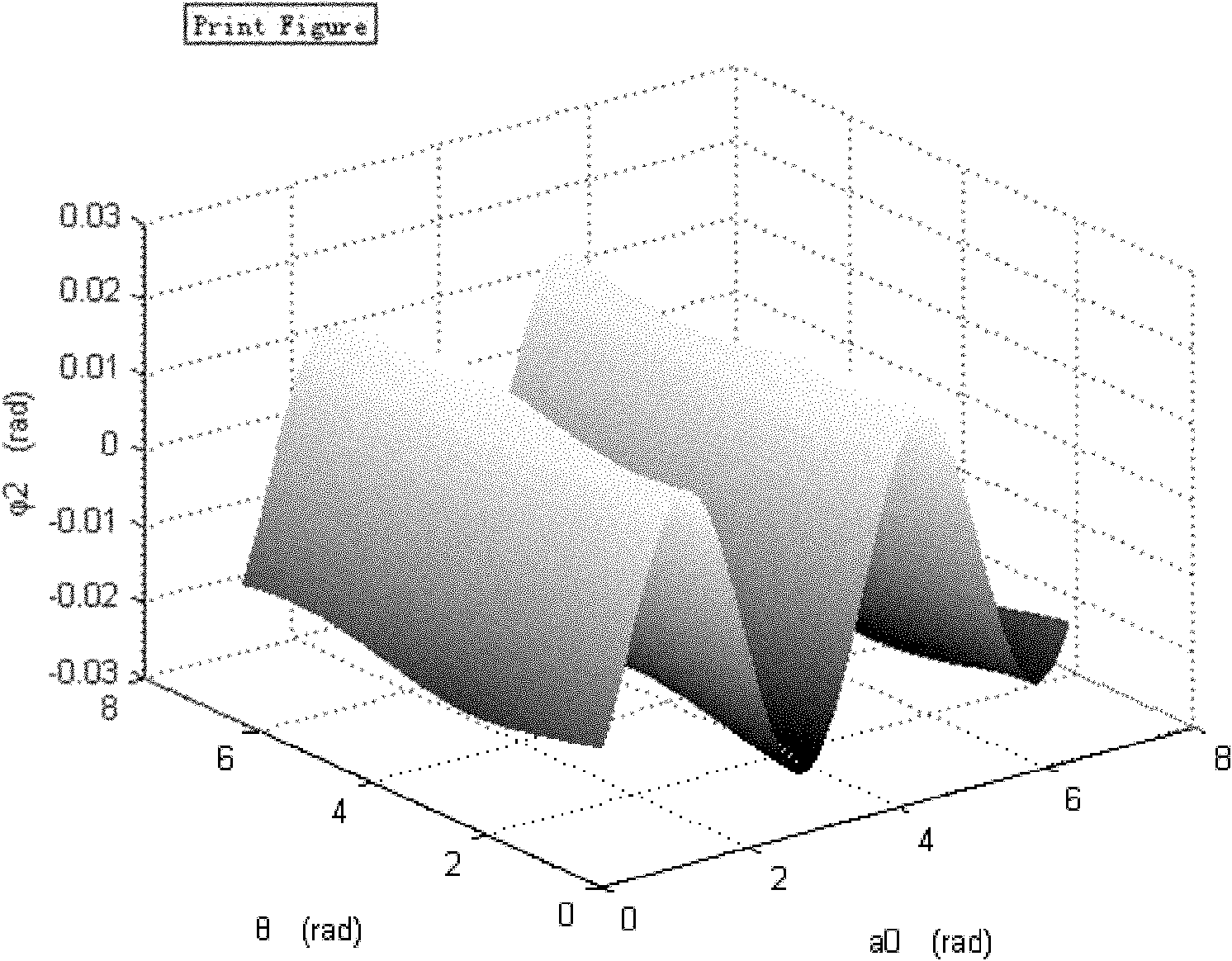
[0032] On the basis of the existing incremental optical encoder, the present invention increases the number of photoelectric read heads of the optical encoder to four, and arranges the four photoelectric read heads evenly along the circumference of the indicating circular grating disk, so that each read head Distributed at 90 degrees relative to the center of the circle. The moiré fringe phase at the position of the four read heads is solved by four read heads, AD conversion circuit and phase detection algorithm, and then based on the phase information of the four specific positions, the vibration direction and the vibration direction of the scale circular grating disk are calculated Vibration amplitude, so as to obtain the error term caused by the vibration and reversely substitute it into the expression of the phase change of the moiré fringe caused by the rotation of the optical encoder, so as to eliminate the influence of the vibration.

[0033] The theoretical basis and e...


PUM


Abstract

The invention aims to provide a method for eliminating the influence of vibration over the measurement of an incremental optical encoder, so as to solve the technical problem of poor anti-vibration ability of the incremental optical encoder in the prior art. The method is characterized in that on the basis of the existing incremental optical encoder, the number of photoelectric read heads of the optical encoder is increased to four; the four photoelectric read heads are evenly settled along the circumference of an indicating circular grating disc; and each read head is distributed at an angle of 90 DEG relative to a circle center. Stacked grating fringe phases in the positions of the four read heads are solved through the four read heads, an analog-digital (AD) conversion circuit and a phase detection algorithm; then the vibration direction and the vibration amplitude of a scale circular grating disc are calculated on the basis of the phase information of the four specific positions, so as to determine error terms produced during the vibration; and the vibration direction and the vibration amplitude are inversely substituted into an expression of stacked grating fringe phase changes caused by the rotation of the optical encoder, so as to eliminate the influence of the vibration. By adopting the method, phase detection errors of the optical encoder are greatly reduced during the vibration, and the measurement accuracy of the optical encoder is improved when the vibration exists.

Description

technical field [0001] The invention relates to a method for improving the measurement stability of an optical encoder, in particular to a method for eliminating the influence of vibration on the measurement of an incremental optical encoder. Background technique [0002] Optical encoder is a modern sensor that combines circular grating mosaic fringes and photoelectric conversion technology to convert the angle value of mechanical rotation into digital information output. It is a precision measurement tool and belongs to optoelectronic devices. Among the angle tools, the optical encoder has the highest angle measurement accuracy, which can reach the second level. [0003] Incremental optical encoder has two grating disks, which are the scale circular grating disk and the indicating circular grating disk respectively. The circumference of the two grating disks is engraved with uniform grating lines. The engraved lines are not parallel, but have a small inclination angle, so ...

Claims


Application Information

Patent Timeline
Patent Type & Authority Patents(China)
IPC IPC(8): G01D5/347
Inventor 朱帆吴易明
Owner XI'AN INST OF OPTICS & FINE MECHANICS - CHINESE ACAD OF SCI
Learn More