Machine tool with a workpiece table

A technology of workpiece table and machine tool, which is applied in the direction of metal processing machinery parts, manufacturing tools, metal processing equipment, etc., and can solve the problems of limited application possibilities

Inactive Publication Date: 2012-09-05
MIKRON AGIE CHARMILLES
View PDF6 Cites 2 Cited by
  • Summary
  • Abstract
  • Description
  • Claims
  • Application Information

AI Technical Summary

Problems solved by technology

The application possibilities of this known device are therefore limited and, depending on the size and weight of the workpiece, in addition to the spring-loaded struts, corresponding embodiments of the piezoelectric table and the piezoelectric actuator are required

Method used


Image

  • Machine tool with a workpiece table
  • Machine tool with a workpiece table
  • Machine tool with a workpiece table

Examples


Embodiment Construction

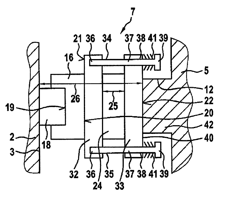
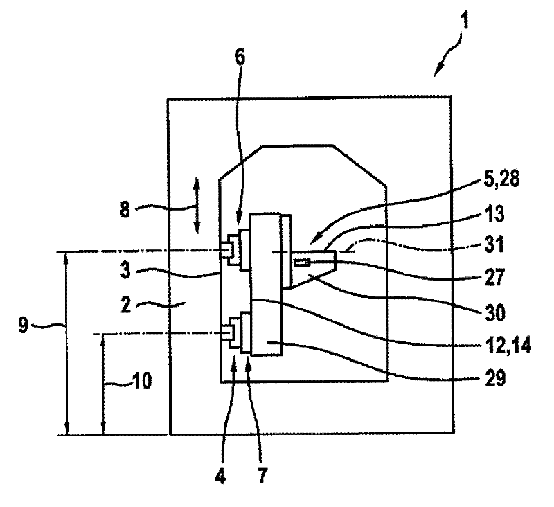
[0026] figure 1 Shows—in schematic form—the parts of a machine tool 1 with a machine frame 2. The frame 2 has a vertical wall 3, and the workpiece table 5 is set on the vertical wall by means of a holding device 4. The holding device 4 has holding elements 6, 7 which are placed at a distance from each other and which—with respect to the vertical direction of the vertical wall 3 (arrow 8)—are positioned at positions 9, 10 of different heights. The workpiece table 5 is held on the machine frame 2 by means of two holding elements 6 and 7.

[0027] in figure 1 In an exemplary embodiment, the workpiece table 5 is realized as a rigid table 11. It has a vertically extending rear side wall 12, and has a table surface 13 extending transversely with respect to the rear side wall 12, especially at a right angle, and the table surface is used to receive an unshown workpiece or an unshown workpiece tray. As you can from figure 1 It can be seen that the workpiece table 5 is held on the frame...


PUM


Abstract

A machine tool having a machine frame and a workpiece table. It is provided that the workpiece table (5), on one of its sides (14), is held on the machine frame (2) by a holding device (4), the holding device (4) having at least two holding elements (6, 7), which are spaced apart from one another on the said side (14) of the workpiece table (5) and which are disposed at differing height positions (9, 10), such that an upper and a lower holding element (6, 7) is realized, and at least one of the holding elements (6, 7) being equipped with at least one piezo actuator (24) for altering its length and, associated therewith, influencing the position of the workpiece table.

Description

Technical field [0001] The invention relates to a machine tool with a frame and a workpiece table. Background technique [0002] In the case of the above-mentioned types of machine tools, because of different workpiece loads and machining loads of the workpiece table, deformation and consequent errors in the machine tool geometry will occur. These geometric errors will reduce the accuracy of the workpiece. The requirements for high precision workpieces and / or greater automation and / or increased productivity make it necessary to eliminate or at least reduce these geometrical errors. Alternatively, or in addition, undesirable vibrations can occur during machining. These vibrations affect the machining output of the machine tool and reduce the accuracy and surface quality of the workpiece. [0003] Known from DE 10 2006 049 867 A1 is a machine tool with a workpiece clamping device on a workpiece table for the purpose of clamping a workpiece. The workpiece holding device can be mov...

Claims


Application Information

Patent Timeline
Patent Type & Authority Applications(China)
IPC IPC(8): B23Q1/26B23Q11/00B23Q23/00
CPCB23Q1/01B23Q1/34B23Q11/001B23Q17/22
Inventor F.布拉奇J.康维卡M.金德勒
Owner MIKRON AGIE CHARMILLES
Why Eureka
Try Eureka