Tire mounting and demounting machine, tire mounting method and tire demounting method

A tire loading and unloading, tire technology, applied in tire installation, tire parts, transportation and packaging, etc., can solve the problems of damage to tires, damage to the bead part of the tire, steel wire and carbon fiber breakage, etc., to prevent damage.

Inactive Publication Date: 2012-09-05
ONODANI KIKO KK
View PDF8 Cites 12 Cited by
  • Summary
  • Abstract
  • Description
  • Claims
  • Application Information

AI Technical Summary

Problems solved by technology

However, in the case of tires reinforced with metal steel wire or carbon fiber in recent years, the rigidity of the tire is further improved compared with the above-mentioned flat tires. Even if the upper bead part is pushed down by the press-fitting roller, insert the protrusion of the bracket head between the upper bead part and the upper bead part of the wheel, and operate the upper bead part and the upper bead part by hand. A crowbar for removing and installing tires is inserted between the rim parts. In order to separate the upper bead part upward from the upper rim part, the protrusion of the above-mentioned bracket head and the crowbar for removing and installing the tire must act strongly on the upper bead part. force, thus damaging the upper bead portion of the tire
In addition, when the tire is mounted on the wheel, the bead roller will press the upper bead portion of the tire with a large pressing force, so the tire may be damaged due to the slippage with the bead roller.
[0010] In this way, if the upper bead portion is damaged, the adhesion between the upper bead portion and the upper bead portion will decrease when the tire is mounted on a wheel, making it difficult to maintain an appropriate air pressure for a long period of time.
[0011] In addition, when the above-mentioned ultra-rigid tire reinforced with steel wire or carbon fiber is pressed by bead rollers on the downstream side of the frame head in the rotation direction and in the vicinity of the frame head, from the upper bead portion of the tire to the The sidewall and shoulder are greatly deformed and sag into a roughly U-shaped or roughly V-shaped, and there is the problem of the above-mentioned steel wire and carbon fiber breaking

Method used


Image

  • Tire mounting and demounting machine, tire mounting method and tire demounting method
  • Tire mounting and demounting machine, tire mounting method and tire demounting method
  • Tire mounting and demounting machine, tire mounting method and tire demounting method

Examples


Embodiment Construction

[0067] Hereinafter, the present invention will be described in more detail with reference to the drawings.

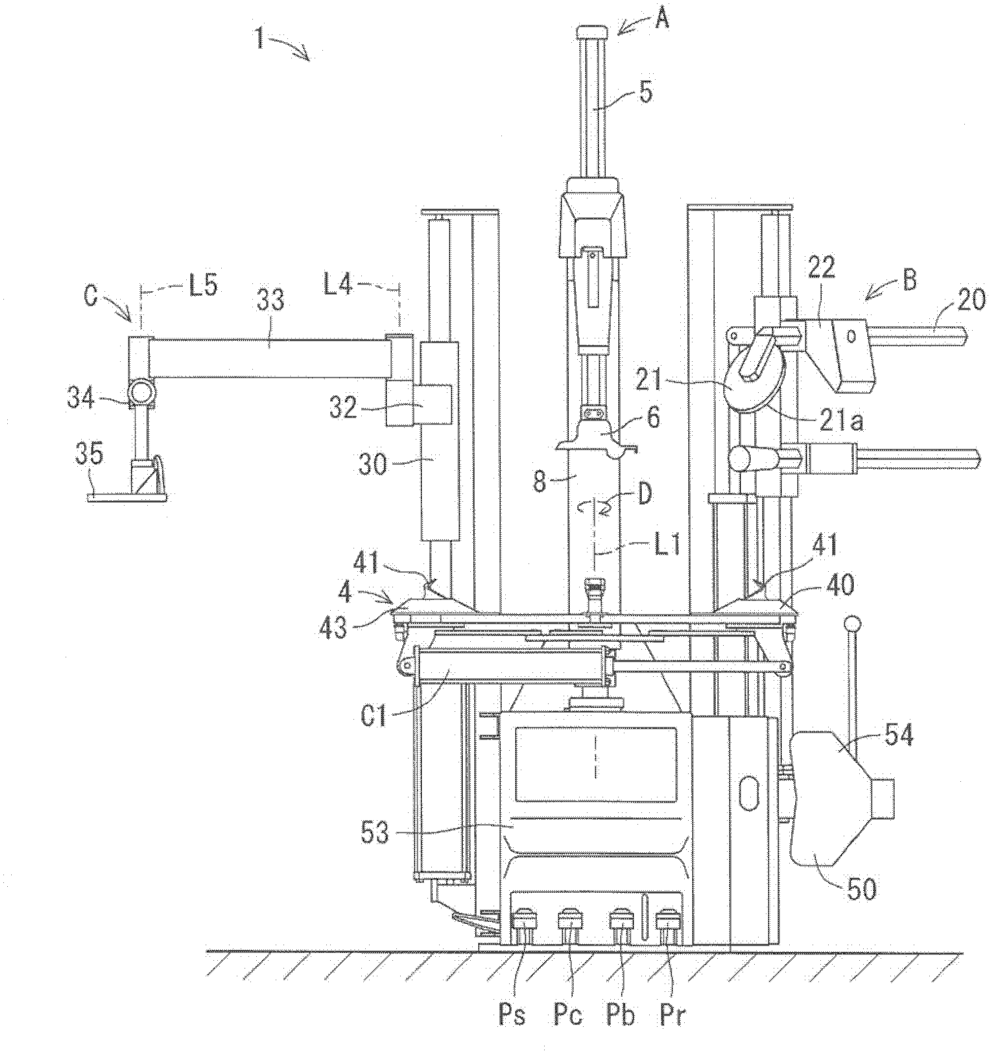
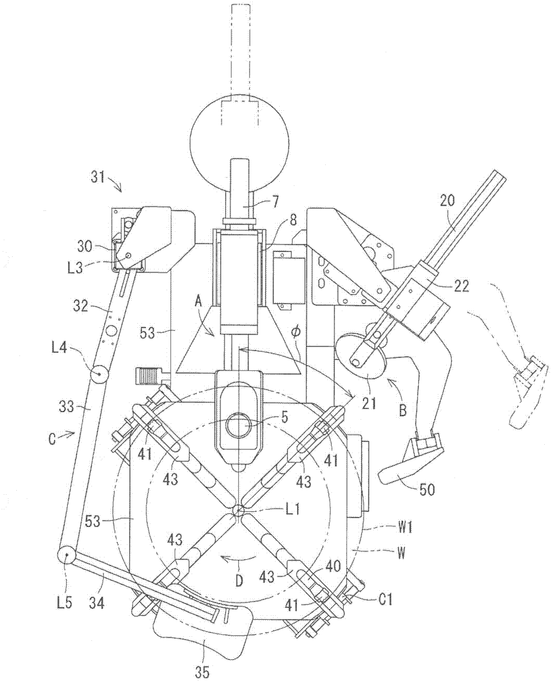
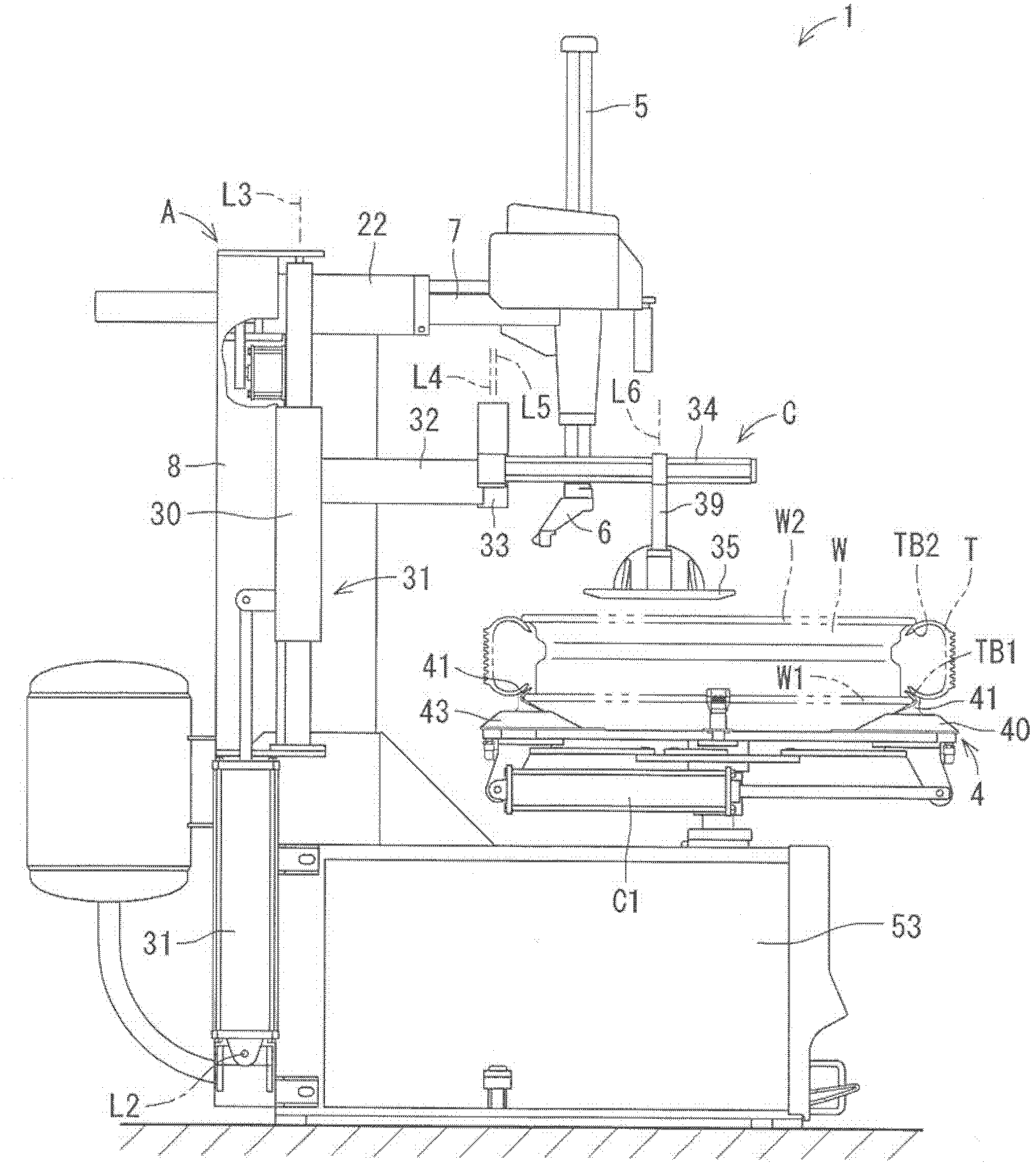
[0068] figure 1 It is a front view showing a tire loading and unloading device 1 according to an embodiment of the present invention, figure 2 for from figure 1 A top view of the tire handling device 1 seen from above, image 3 for from figure 1 The left side view of the tire handling device 1 seen from the left, Figure 4 for from figure 1 The right side view of the tire handling device 1 seen from the right side. The tire loading and unloading device 1 of the present embodiment is used to implement a tire mounting method and a tire detaching method. The tire loading and unloading device 1 of the present embodiment basically includes a bead portion guiding device A, a bead press device B, and a mount press device C. As shown in FIG.

[0069] First, the configuration of the bead portion guiding device A will be described. The bead portion guide device A include...


PUM


Abstract

A tire mounting and demounting machine includes a turntable that holds a lower rim portion of a wheel in a detachable state and rotating the wheel about a vertical rotation axial line, a bead guiding member that guides lower and upper bead portions of a tire to fit the lower or upper bead portion to an upper rim portion of the wheel and guides the upper bead portion of the tire, which is fitted to the upper rim portion of the wheel, to be demounted from the upper rim portion, and a bead roller having a pressing surface extending in a direction going away from the rotation axial line, that presses the upper bead portion of the tire mounted on the wheel from above by the pressing surface at a location on a downstream side from the bead guiding member in a rotating direction of the turntable.

Description

technical field [0001] The present invention relates to a tire loading and unloading device capable of detaching a tire from a wheel and mounting the tire on the wheel, a tire mounting method and a tire detaching method. Background technique [0002] A typical prior art is described in, for example, Japanese Patent Application Laid-Open No. 6-255328. In this prior art, since it is difficult to remove and install a high-rigidity tire called a flat tire from a wheel by manpower, a tire loading and unloading device called a tire changer or a tire changer is used. Such a tire loading and unloading device is disclosed in, for example, Japanese Patent Application Laid-Open No. 6-255328. [0003] In this prior art, when the tire is removed from the rim, the pressing arm is lowered to rotate the turntable, and the upper bead and sidewall of the tire are pushed down by the bead rollers to rotate the turntable. At the same time, make the above-mentioned upper bead fall into the conc...

Claims


Application Information

Patent Timeline
Patent Type & Authority Applications(China)
IPC IPC(8): B60C25/132
CPCB60C25/138
Inventor 三村义雄
Owner ONODANI KIKO KK
Why Eureka
Try Eureka