Clean room

A technology of clean room and clean area, applied in the field of clean room, can solve the problems of large air circulation, differential temperature distribution, etc., and achieve the effect of simple leakage test

Active Publication Date: 2015-07-01
ASAHI INDSHA
View PDF2 Cites 0 Cited by
  • Summary
  • Abstract
  • Description
  • Claims
  • Application Information

AI Technical Summary

Problems solved by technology

However, in the case of non-unidirectional type, even if the supply air temperature is controlled in order to deal with the heat load required in the clean area 41, there is a difference between directly below the filter unit 51 and outside it. Temperature Distribution
[0008] In order to control the diffusion of the particles generated in the clean area 41 and remove the heat from the equipment of the manufacturing facility M, etc., the face velocity of the downflow needs to be 0.15 to 0.5 m / sec. Figure 8 In the unidirectional flow type, there is a problem that a large amount of air circulation is required

Method used


Image

  • Clean room
  • Clean room
  • Clean room

Examples


Embodiment Construction

[0036] A preferred embodiment of the present invention will be described in detail below based on the drawings.

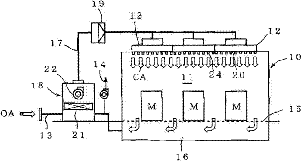
[0037] figure 1 An overall view showing the clean room of the present invention.

[0038] First, the clean room 10 is configured such that a plurality of air supply chambers 12 are arranged adjacent to each other over substantially the entire surface of the ceiling of the clean area 11 where the manufacturing equipment M is installed. The return chamber 16 connects the return chamber 16 and the air supply chamber 12 to a circulation path 17 , and the circulation path 17 is connected to an air conditioner 18 .

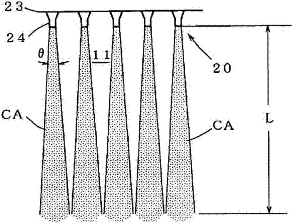
[0039] In the present embodiment, a high-performance filter (HEPA or ULPA) 19 is provided on the circulation path 17, and a plurality of flat nozzles 20 are provided at the opening of the air supply chamber 12 to form a discharge port.

[0040] The air conditioner 18 has an evaporator 21 and a circulation fan 22, an introduction line 13 of outside air OA ...


PUM


Abstract

Provided is a clean room wherein a necessary speed of a down flow can be ensured even if a circulating air volume is small, and furthermore, filter leak test can be easily performed. Ports for blowing out temperature-controlled cleaned air to the clean zone (11) in a clean room (10) are formed using a plurality of plate nozzles (20).

Description

technical field [0001] The present invention relates to a clean room used in semiconductor manufacturing, liquid crystal substrate manufacturing, pharmaceutical and food manufacturing, etc., and particularly relates to a clean room with an improved outlet for discharging clean air with a fine temperature adjustment to the clean area. Background technique [0002] In manufacturing plants such as semiconductor manufacturing, liquid crystal substrate manufacturing, pharmaceuticals and food manufacturing, etc., the entire building is made into a clean room. [0003] As a clean room, there is Figure 8 The unidirectional flow shown (laminar flow) and Figure 9 The two methods shown are non-unidirectional (turbulent flow). [0004] Figure 8 The illustrated unidirectional flow type clean room 40 is configured such that an air supply chamber 42 is provided across substantially the entire surface of the ceiling of a clean area 41 in which the manufacturing equipment M is installed,...

Claims


Application Information

Patent Timeline
Patent Type & Authority Patents(China)
IPC IPC(8): F24F7/06
CPCF24F3/161F24F3/167F24F7/06F24F7/10
Inventor 蕨野慎治和气清隆中村元彦村山民树
Owner ASAHI INDSHA
Why Eureka
Try Eureka