Centering device on roll gang

A technology of centering device and conveying roller table, applied in the direction of roller table, conveyor objects, transportation and packaging, etc., can solve the problems of scattered steel parts, reduce production efficiency, affect the quality of conveying steel parts, etc., to improve conveying quality, The effect of improving production efficiency

Active Publication Date: 2012-09-12
TJK MACHINERY TIANJIN
View PDF5 Cites 9 Cited by
  • Summary
  • Abstract
  • Description
  • Claims
  • Application Information

AI Technical Summary

Problems solved by technology

[0004] The above prior art has the following defects: when conveying slender single or very few steel bars, the width of the steel bar conveying roller table is relatively narrow, and there are erected baffles on both sides of the steel bar conveying roller table, which limit the slender The steel bar slips and falls out of the conveying roller table; but when conveying large batches of steel bar parts or steel parts with a large size, the width of the conveying roller table needs to be greater than the width of the conveyed steel bar parts, and then on both sides of the conveying roller table It is not convenient to stack and collect reinforcement parts when the baffle is erected
Therefore, due to the inertia during transportation, it is impossible for steel parts to run in a straight line along the conveying rollers. Often, the conveyed steel parts are scattered or deviated midway and slip out of the conveying roller table, which directly affects the conveying quality of steel parts and reduces production efficiency.

Method used


Image

  • Centering device on roll gang
  • Centering device on roll gang
  • Centering device on roll gang

Examples


Embodiment Construction

[0016] Embodiments of the present invention will be further described below in conjunction with the accompanying drawings.

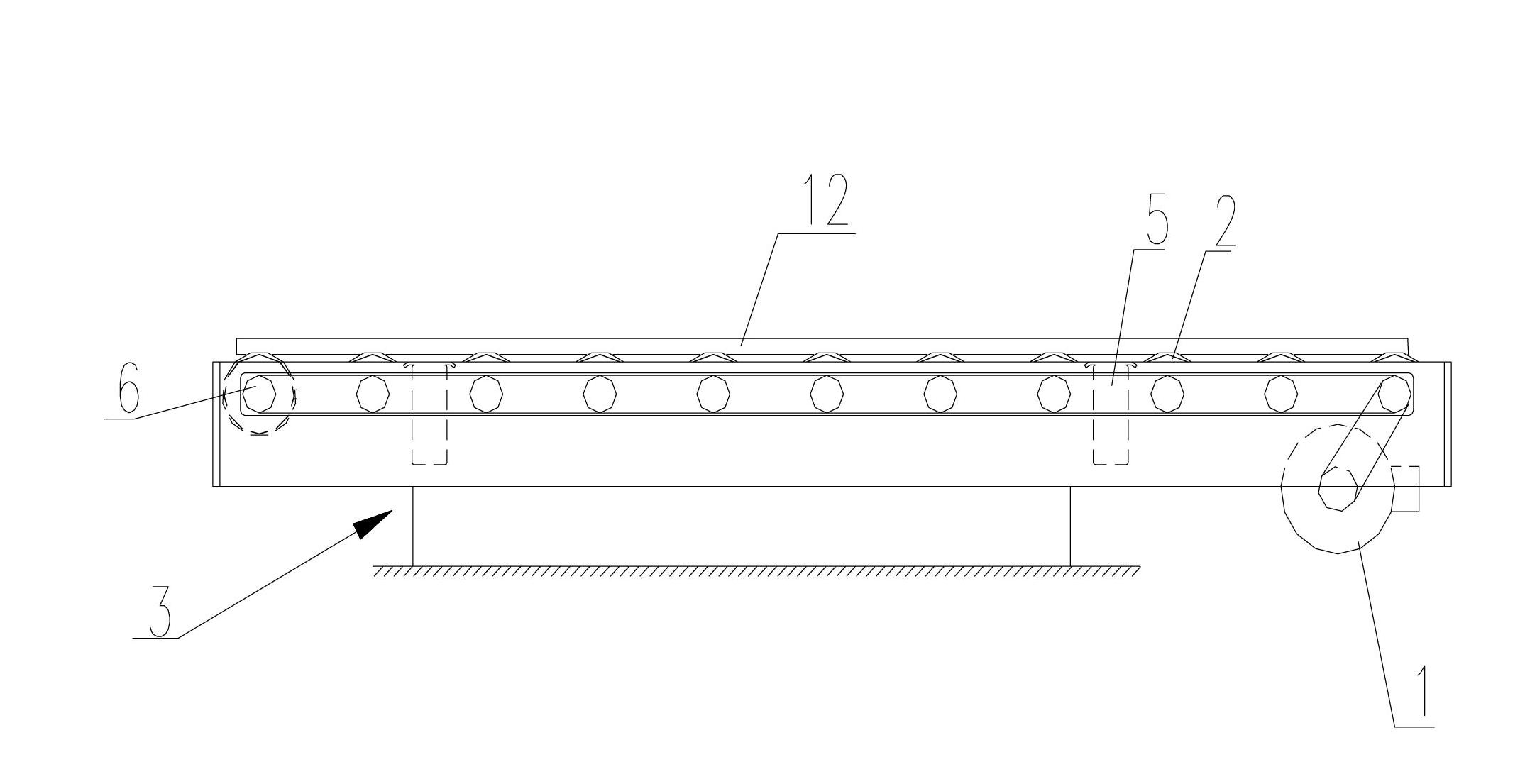
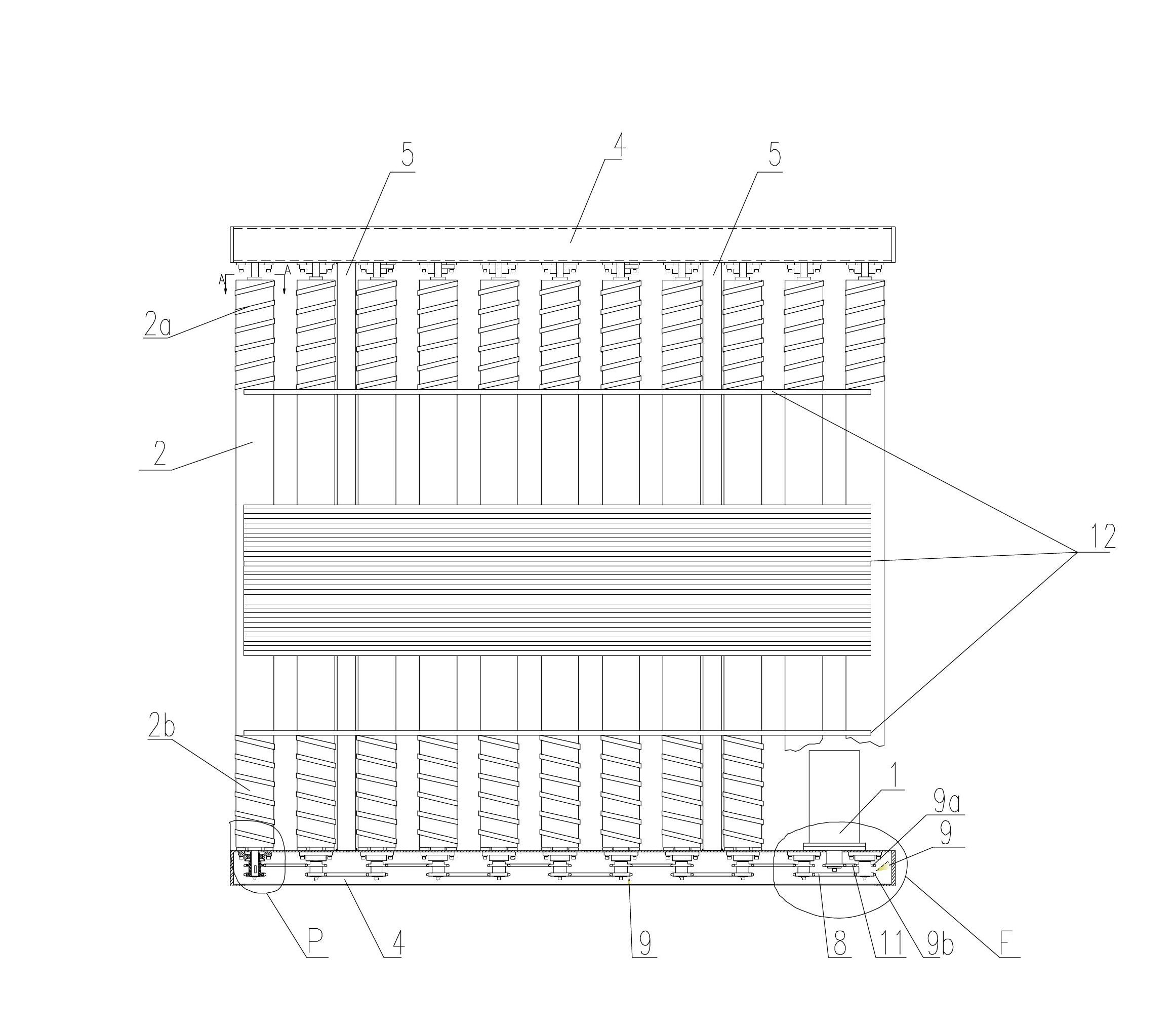
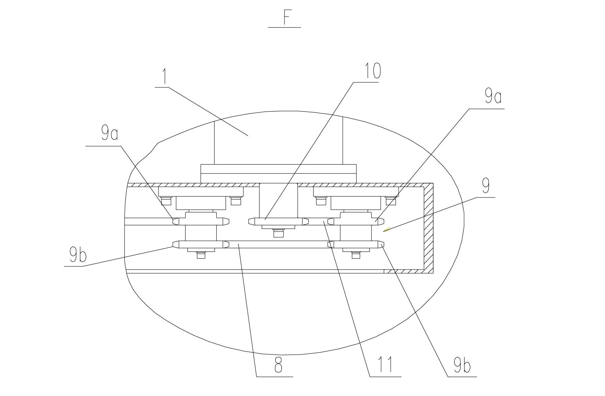
[0017] figure 1 is the front view of the structure of the present invention; figure 2 yes figure 1 top view of image 3 yes figure 2 Enlarged view of part F in ; Figure 4 yes figure 2 Enlarged view of part P in ; Figure 5 yes figure 1 Middle A-A sectional view.

[0018] As shown in the figure, the present invention provides a centering device on the conveying roller table. The centering device on the conveying roller table includes: a frame 3; two side support frames 4 located symmetrically on both sides of the frame 3; A plurality of conveying rollers 2 that rotate parallel to each other are arranged at intervals between the two side support frames 4 .

[0019] The same side of each delivery roller 2 between the two side support frames 4 is provided with a left helical belt 2b, and the same side of each delivery roller 2 is provided with a...


PUM


Abstract

The invention discloses a centering device on a roll gang. The centering device on the roll gang comprises: a rack; two side supports arranged on two sides of the rack; and a plurality of conveying rolls which are supported between the two side supports in a hinge joint way, arranged at intervals, and are mutually rotated in parallel, wherein left spiral bands are respectively arranged on the same sides of the conveying rolls between the two side supports; right spiral bands are respectively arranged on the same other sides of the conveying rolls; and the left spiral bands and the right spiral bands are bulges which have same structures and opposite rotation directions, are fixed on the conveying rolls and are spiral. The centering device on the roll gang has the beneficial effects that: the left spiral bands and the right spiral bands are used for pushing dispersed reinforcing steel bar parts into the middle part of the conveying rolls along with the rotation of the conveying rolls in a conveying process; and the reinforcing steel bar parts can be brought in the middle part of the conveying rolls along with the rotation of the left spiral bands and the right spiral bands when being fallen into spiral coils of the left spiral bands and the right spiral bands, so that the phenomenon that the reinforcing steel bar parts are dispersed or are slipped off the conveying rolls in midway is avoided, and the conveying quality and the production efficiency of the reinforcing steel bar parts are improved.

Description

technical field [0001] The invention relates to a conveying roller table, in particular to a centering device on the conveying roller table. Background technique [0002] With the in-depth development of economic construction, the demand for steel products has also increased, especially in the fields of construction, roads, bridges and transportation. The use of mechanized production instead of manually processed steel parts has become popular. Therefore, a batch of Companies that automate the processing of steel parts are growing rapidly. [0003] At present, most of the processing of steel bar parts has been completed on automatic equipment, and the transportation of steel bar parts is carried out automatically by means of conveyor rollers. The structure of the steel bar conveying roller table in the prior art includes: a frame; a plurality of conveying rollers; the two ends of the plural conveying rollers are rotatably supported on both sides of the frame; Sprocket, the...

Claims


Application Information

Patent Timeline
Patent Type & Authority Applications(China)
IPC IPC(8): B65G13/07B65G13/11B65G47/22
Inventor 陈振东
Owner TJK MACHINERY TIANJIN
Why Eureka
Try Eureka