Engine exhaust gas energy recovery system

An energy recovery, engine cylinder technology, applied in engine components, combustion engines, machines/engines, etc., can solve the problems of single cooling and heating purposes, low energy conversion efficiency of thermoelectric power generation, and low exhaust energy grade, etc., and achieve improvement. The overall oil consumption level, the effect of improving the performance under low working conditions, and increasing the output power

Inactive Publication Date: 2012-09-12
SHANGHAI JIAO TONG UNIV
View PDF5 Cites 6 Cited by
  • Summary
  • Abstract
  • Description
  • Claims
  • Application Information

AI Technical Summary

Problems solved by technology

Due to the characteristics of low grade and difficult recovery of exhaust gas energy, there are still many problems in some existing technologies, such as the low energy conversion efficiency of using temperature difference to generate electricity, the implementation process of fuel catalytic reforming technology is relatively difficult, and the use of waste heat The purpose of cooling and heating is relatively simple, the scope of application of the power turbine is relatively narrow, and the structure of the subsequent power cycle device is relatively complicated, etc.
[0003] After searching the existing technical documents, it w

Method used


Image

  • Engine exhaust gas energy recovery system
  • Engine exhaust gas energy recovery system

Examples


Embodiment

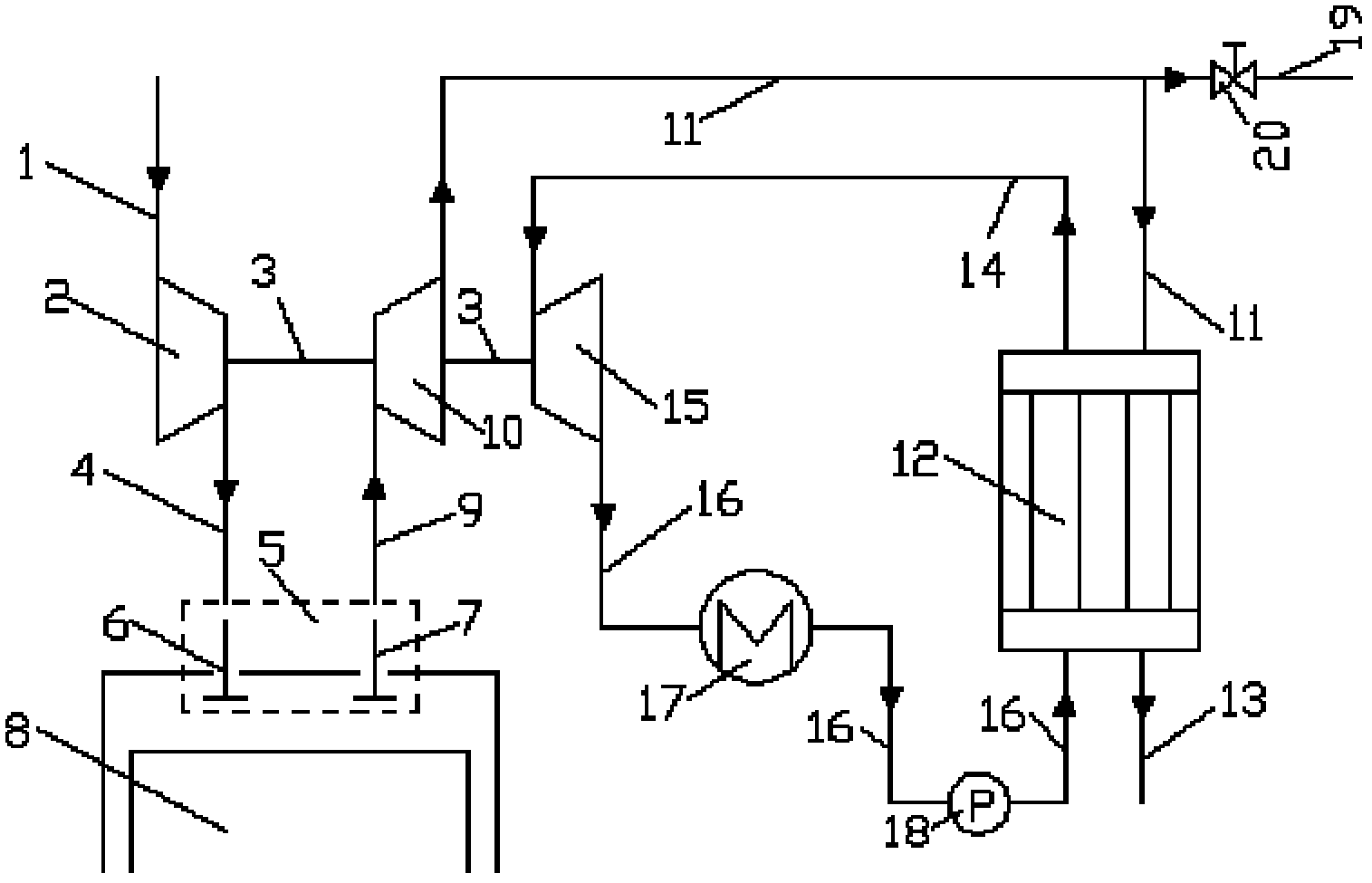
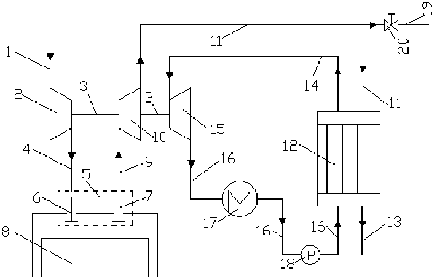
[0013] like figure 1 Shown, the present invention comprises: compressor intake pipe 1, compressor 2, connecting shaft 3, compressor outlet pipe 4, engine gas distribution mechanism 5, engine intake valve 6, engine exhaust valve 7, engine cylinder 8, the first A turbine inlet pipe 9, a first turbine 10, a first turbine outlet pipe 11, a heat exchanger 12, an exhaust pipe 13, a second turbine inlet pipe 14, a second turbine 15, a second turbine outlet pipe 16, and a condenser 17 , booster pump 18, bleed pipe 19 and bleed valve 20, the air inlet and outlet of compressor 2 are connected with the air outlet of compressor inlet pipe 1 and the air inlet of compressor outlet pipe 4 respectively, and the engine valve mechanism 5 is installed On the engine cylinder 8, the air outlet of the compressor air outlet pipe 4 and the air inlet of the first turbine intake pipe 9 are all connected with the engine cylinder 8, and the air inlet and outlet of the first turbine 10 are connected with ...


PUM


Abstract

The invention provides an engine exhaust gas energy recovery system in the technical field of internal combustion engines, which comprises an engine cylinder, a gas compressor, turbines, a heat exchanger, a condenser and a booster pump, wherein the gas compressor, a first turbine and a second turbine are coaxially connected through connecting shafts; a gas outlet of a gas outlet pipe of the first turbine, a gas inlet of an exhaust pipe of the first turbine, a gas inlet of a gas inlet pipe of the second turbine and a gas outlet of a gas outlet pipe of the second turbine are all connected with the heat exchanger; and the condenser and the booster pump are sequentially mounted in the gas outlet pipe of the second turbine along the fluid flow direction. In the working process of an engine, flow media flowing through the second turbine are heated by engine exhaust gas flowing out of the first turbine in the heat exchanger and are enabled to expand and do work in the second turbine, so that more available energy can be obtained by the gas compressor, the gas inlet flux of the engine is increased and the output power is improved. The engine exhaust gas energy recovery system is reasonable in design and simple in structure, and is suitable for a turbocharging system in which the gas compressor is coaxially connected with the two turbines.

Description

technical field [0001] The invention relates to a turbocharging system in the field of internal combustion engines, in particular to an engine exhaust energy recovery system in which a compressor and two turbines are coaxially connected. Background technique [0002] From the current heat balance of the engine, the power used for power output only accounts for 40%-50% of the total heat of fuel combustion (diesel engine) or 25%-40% (gasoline engine), and other heat is discharged into the engine through the cooling system and exhaust gas. atmospheric environment. Therefore, recycling engine waste heat is an effective way to improve engine thermal efficiency. From the perspective of domestic and foreign exhaust energy utilization technologies, there are refrigeration, heating, thermoelectric power generation, fuel catalytic reforming, power turbine, and power cycle device. Due to the characteristics of low grade and difficult recovery of exhaust gas energy, there are still ma...

Claims


Application Information

Patent Timeline
IPC IPC(8): F02B37/04F01L1/34
CPCY02T10/12
Inventor 朱思鹏邓康耀崔毅曲栓
Owner SHANGHAI JIAO TONG UNIV
Why Eureka
Try Eureka