Ram type engine air intake system for vehicle

A vehicle engine and air intake system technology, which is applied to engine components, machines/engines, charging systems, etc., can solve problems such as reduced engine efficiency, inability to generate intake pressure, and inability to overcome filter engine intake requirements, etc. Achieve the effect of eliminating efficiency reduction and increasing intake air flow

Pending Publication Date: 2018-05-08
李桂江
View PDF0 Cites 0 Cited by
  • Summary
  • Abstract
  • Description
  • Claims
  • Application Information

AI Technical Summary

Problems solved by technology

The disadvantage of the natural air intake system is: most of the air intake openings are set inside the car body, the air intakes are very small, and there is no stamping effect
For some air filters installed outside the car body, the air intakes do not open forward, and the air intakes are very small and have no stamping effect, so they cannot generate enough air intake pressure to overcome the resistance of the filter to meet the requirements of the engine. Air intake requirements
Especially when the engine is running at high speed, the air intake flow increases, and the resistance of the filter screen increases with the increase of the air flow, resulting in insufficient air supply, reduced engine efficiency, and serious exhaust pollution.
The winter temperature in the north is low, which reduces the efficiency of the engine and increases the fuel consumption
Achilles heel of high temperature and flammability in turbocharger

Method used


Image

  • Ram type engine air intake system for vehicle
  • Ram type engine air intake system for vehicle
  • Ram type engine air intake system for vehicle

Examples


Embodiment 1

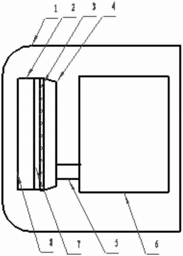
[0033] Such as figure 1 As shown, an air intake filter 3 is arranged on one side of the water tank air outlet surface 7, and is connected to one side of the water tank air outlet surface by a connecting member. The other side of the air intake filter screen is provided with a chamber 4, which is connected with the engine air intake through a pipeline. It constitutes a ram type air intake system for air intake on one side of the air outlet side of the water tank. The high-speed air flow passing through the water tank is used to provide pressurized air intake for the engine, and the temperature of the water tank is used to heat the air passing through the water tank, which solves the problem of low engine air intake pressure and low engine air intake temperature in winter and high fuel consumption. It can improve engine efficiency, reduce fuel consumption and emission pollution.

Embodiment 2

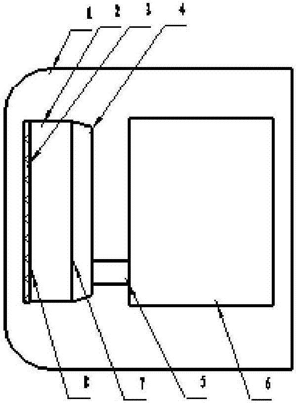
[0035] Such as figure 2 As shown, the filter screen 3 is set on the air inlet surface of the water tank

Embodiment 3

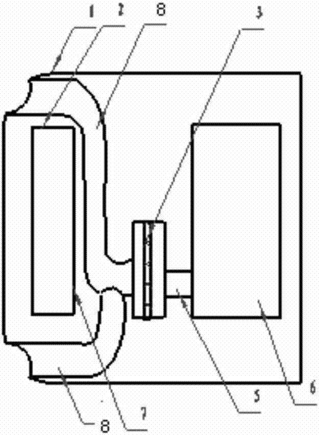
[0037] Such as image 3 As shown, the filter screen 3 is arranged behind the water tank, and its air inlet is the air inlet chamber formed by the air intake duct 8 on both sides of the water tank 2 .


PUM


Abstract

The invention discloses a ram type engine air intake system for a vehicle. A filter net of the air intake system is arranged at the windward position of a vehicle body, or the outer part of the vehicle body is provided with an air filter air inlet with a forward opening. Filtered air enters an engine air inlet pipe via a cavity or a pipeline. The filter net or the air filter air inlet is arrangedat the air outlet side of a water tank. The filter net or the air filter air inlet is arranged at the air inlet side of the water tank. An air inlet duct or an air filter is arranged at the outer partof the vehicle body or at any side or both sides of the water tank. All or part of air passing the air inlet duct or the air filter enters an engine after being heated by the inner part of the watertank, or the rear part of the water tank, or the upper part of the water tank, or the inner part of an engine exhaust pipe or the periphery of the exhaust pipe. The ram type engine air intake system has the beneficial effects that high-speed air flow forms shock pressure on the filter net, overcomes the resistance of the filter net and increases air intake flow, and the problem that insufficient air supply causes low engine efficiency, high energy consumption, severe exhaust pollution and the like is solved.

Description

technical field [0001] The invention relates to the technical field of vehicle engines, in particular to a ram type vehicle engine air intake system. Background technique [0002] The existing vehicle engine intake system is a natural intake or turbocharged intake structure. The disadvantage of the natural air intake system is that most of the air intake openings are set inside the car body, and the air intake openings are very small and have no stamping effect. For some air filters installed outside the car body, the air intakes do not open forward, and the air intakes are very small and have no stamping effect, so they cannot generate enough air intake pressure to overcome the resistance of the filter to meet the requirements of the engine. Air intake requirements. Especially when the engine is running at high speed, the air intake flow increases, and the resistance of the filter screen increases with the increase of the air flow, resulting in insufficient air supply, re...

Claims


Application Information

Patent Timeline
IPC IPC(8): F02M35/10
CPCF02M35/10006F02M35/10157F02M35/10268
Inventor 李桂江
Owner 李桂江
Why Eureka
Try Eureka