
Liquid nitrogen filling device and liquid nitrogen filling system

A filling device and liquid nitrogen technology, applied in the pipeline system, gas/liquid distribution and storage, mechanical equipment, etc., can solve the problems of increased labor intensity, single use, and difficulty in popularization and application, so as to reduce labor intensity and improve sealing effect, easy-to-use effect

Active Publication Date: 2014-04-02
TIME MEDICAL JIANGSU
View PDF5 Cites 1 Cited by
  • Summary
  • Abstract
  • Description
  • Claims
  • Application Information

AI Technical Summary

Problems solved by technology

[0002] In the past ten years, in order to ensure the normal operation of high-temperature superconducting radio frequency coils, the technology of using liquid nitrogen vaporization to absorb heat to achieve cooling has developed rapidly. It is easy to use and has a large flow rate, but the liquid nitrogen pump is not compatible with the magnetic resonance system. The infusion tube cannot be used with the high-temperature superconducting radio frequency coil during the infusion process. The liquid nitrogen tank is pressurized by injecting air during the infusion process, causing a large amount of water vapor When it enters the liquid nitrogen tank, it will freeze and block the liquid nitrogen transmission. The infusion process is controlled by manual operation, which increases labor intensity. The infusion tube and the injector are set in one piece. There are placement problems during transportation. It is single-use and difficult to popularize.

Method used


Image

  • Liquid nitrogen filling device and liquid nitrogen filling system
  • Liquid nitrogen filling device and liquid nitrogen filling system
  • Liquid nitrogen filling device and liquid nitrogen filling system

Examples


Embodiment Construction

[0023] The present invention will be described in further detail below in conjunction with the accompanying drawings.

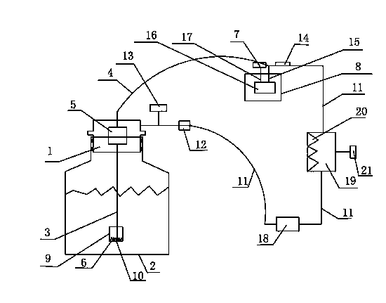
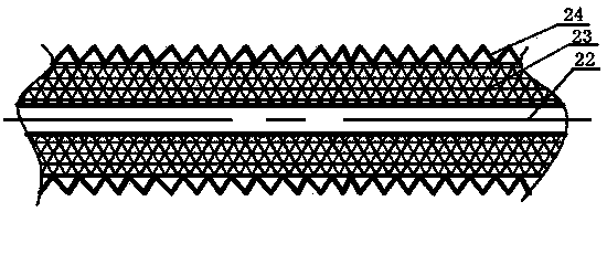
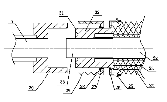
[0024] Such as figure 1 , figure 2 and image 3 As shown, a liquid nitrogen filling device includes a filler 1, a liquid nitrogen tank 2, a liquid inlet pipe 3, a liquid outlet pipe 4, an electromagnetic pump system 18, an air intake device and a safety device, and the air intake device includes Inlet pipe 11 and air inlet joint 12, the safety device is a safety valve 13, the filler 1 is arranged on the upper end of the liquid nitrogen tank 2, the outlet pipe 4 and the inlet pipe 3 are separated from the filler 1 One-piece structure, and in a flexible connection state, the liquid outlet pipe 4 includes a hose 22, a thermal insulation sleeve 23 and a bellows 24, and the liquid inlet pipe 3 and the liquid outlet pipe 4 are connected by an inlet and outlet pipe Head 5, the connection head 5 of the inlet and outlet pipes is arranged inside the filler 1, and ...


PUM


Abstract

The invention discloses a liquid nitrogen filling device and a liquid nitrogen filling system. The liquid nitrogen filling device comprises a filler (1), a liquid nitrogen tank (2), a liquid feeding pipe (3), a liquid discharging pipe (4), an electromagnetic pump system (18), an air feeding device and a safety device, wherein the liquid discharging pipe (4) and the liquid feeding pipe (3) as well as the filler (1) are of a split type structure, and are in movable connection state, a filter device (6) is arranged at one end of the liquid feeding pipe (3), a rapid joint (7) is arranged at one end of the liquid discharging pipe (4), a high-temperature superconduction radio-frequency coil (8) is arranged at one end of the rapid joint (7), a control device is arranged at the other end of the high-temperature superconduction radio-frequency coil (8), an automatic air bleeding device (19) is arranged at one end of the control device, and the filler (1) is connected with the liquid nitrogen tank (2) by a sealing-fixing device. Due to the adoption of the structure, the high-temperature superconduction radio-frequency coil can be filled with liquid automatically, the safety of operators is ensured, the labor intensity of workers is alleviated, the purpose of long-time continuous work is realized, and liquid nitrogen filling device can be compatible with a magnetic resonance system.

Description

technical field [0001] The invention relates to a liquid nitrogen filling device, in particular to a liquid nitrogen filling device for a magnetic resonance imaging system. The invention also relates to a liquid nitrogen filling system. Background technique [0002] In the past ten years, in order to ensure the normal operation of high-temperature superconducting radio frequency coils, the technology of using liquid nitrogen vaporization to absorb heat to achieve cooling has developed rapidly. It is easy to use and has a large flow rate, but the liquid nitrogen pump is not compatible with the magnetic resonance system. The infusion tube cannot be used with the high-temperature superconducting radio frequency coil during the infusion process. The liquid nitrogen tank is pressurized by injecting air during the infusion process, causing a large amount of water vapor When it enters the liquid nitrogen tank, it will freeze and block the liquid nitrogen transmission. The infusion...

Claims


Application Information

Patent Timeline
Patent Type & Authority Patents(China)
IPC IPC(8): F17D1/02F17D3/01
Inventor 徐光福涂炜旻胡长伍刘尊钢高而震马启元
Owner TIME MEDICAL JIANGSU
Learn More