Ceiling system with integrated equipment support structure

一种天花板、设备的技术,应用在具有集成设备支撑结构的天花板系统领域,能够解决昂贵定制安装等问题,达到成本效率高的效果

Inactive Publication Date: 2012-09-12
HUNTAIR
View PDF3 Cites 11 Cited by
  • Summary
  • Abstract
  • Description
  • Claims
  • Application Information

AI Technical Summary

Problems solved by technology

However, this setup suffers from the same problems as hard-wired ventilation: it is expensive, requires custom installation during building construction, and can limit possible room configurations based on the nature of the underlying building frame

Method used


Image

  • Ceiling system with integrated equipment support structure
  • Ceiling system with integrated equipment support structure
  • Ceiling system with integrated equipment support structure

Examples


Embodiment Construction

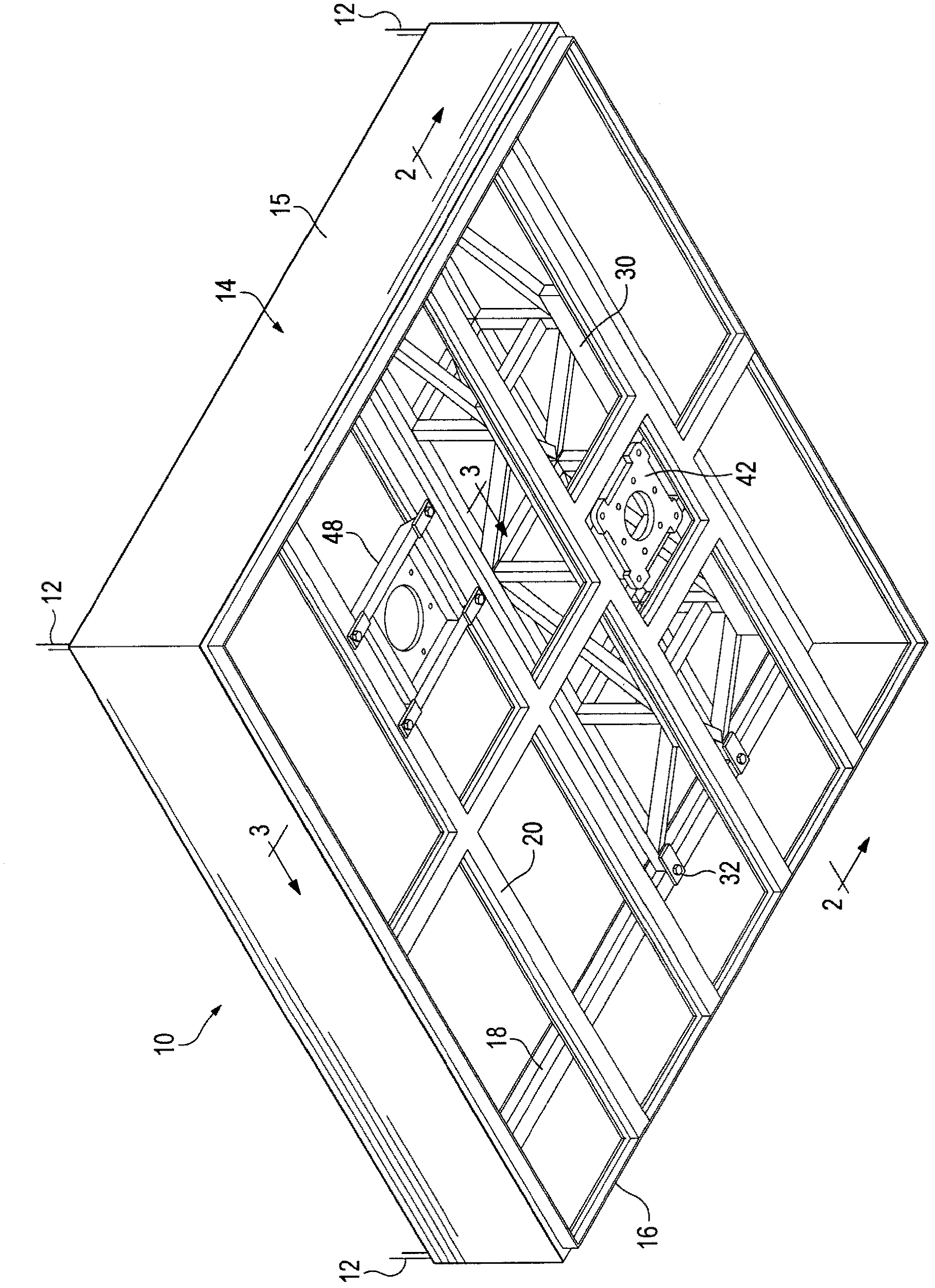
[0018] now go to figure 1 , describes a modular unit employing the present invention. The plenum 10 may be suspended from scaffolding 12, which in turn is attached directly to the I-beam or other frame of the building. The trellis 12 may also be attached to a second structure (not shown), which in turn is attached to the frame of the building. This arrangement allows the plenum 10 to be located at a location other than directly below the structural beams of the building. Alternatively, the plenum 10, in addition to being suspended from the scaffolding 12, may be threaded directly to a portion of the building or to an adapter. Shelves 12 are shown at the corners of the plenum 10, but could be positioned at other locations, or with greater spatial frequencies than shown.

[0019] The plenum 10 is formed from a perimeter 14 of common sheet steel material using methods known in the art, although any sufficiently rigid material will do. The plenum 10 is typically rectangular or...


PUM


Abstract

A modular air-handling plenum for capable of supporting surgical apparatus or other objects is disclosed. The plenum is usually rectangular, may be formed of sheet metal, and features a truss spanning the width of the plenum to carry the weight of the apparatus. The plenum itself is attached to the ceiling of a room. An air handling component may be included to provide filtered and / or conditioned air in the vicinity of the suspended apparatus, or the plenum may be used strictly as an apparatus support, with no air-conditioning function. An ordinary suspended ceiling may also be mounted in the plenum for continuity with the remainder of the room.

Description

[0001] Cross-reference related patent applications [0002] This application claims priority to US Patent Application 12 / 589,475, filed on October 22, 2009, the entire contents of which are incorporated herein by reference. technical field Background technique [0003] Certain indoor environments, such as clean rooms and operating rooms, radiology rooms, and dental suites like those found in hospitals, often require clean air to protect the work performed within them. Such a room may also have different heating or cooling needs at different points within the room. For example, electronic equipment may generate excessive heat and therefore require cooling air to gather near it. Surgeons may also find it advisable to have additional heated or cooled air available in the vicinity of the operating table, so that the patient is kept at a stable temperature, or dissipated by lights or by doctors or nurses surrounding the patient Excessive heat generated by the team. However, th...

Claims


Application Information

Patent Timeline
Patent Type & Authority Applications(China)
IPC IPC(8): E04B9/06F24F7/04E04F19/08
CPCE04B9/006E04B9/0478F24F13/32F24F2221/14E04B9/06E04F19/08F24F7/04
Inventor 扎瑞·库尔塞吉凯文·史瑞伯大卫·鲍尔
Owner HUNTAIR
Why Eureka
Try Eureka