Angle setting device, signal indication light unit, and illuminator unit

A technology for fixing devices and lighting devices, applied in lighting devices, components of lighting devices, lighting applications, etc., can solve the problems of reduced durability of angle fixing devices, low durability and easy deterioration of angle fixing devices, and achieve Reduced load, reliable sealing, and improved durability

Inactive Publication Date: 2012-09-12
PATO RAITO KK
View PDF2 Cites 1 Cited by
  • Summary
  • Abstract
  • Description
  • Claims
  • Application Information

AI Technical Summary

Problems solved by technology

[0006] In Patent Document 1, since the first annular tooth row and the second annular tooth row are exposed to the outside, they are easily deteriorated and damaged during use, and the durability of the angle fixing device is low.
[0007] Particularly, when the first annular dentition and the second annular dentition exposed to the outside are formed of synthetic resin, the synthetic resin is easily affected by external ultraviolet rays, oil, etc., so the first annular dentition and the second annular dentition are formed of synthetic resin. The durability of the second annular tooth row, and thus the durability of the angle fixation device, is further reduced
[0008] In addition, the same problem exists in the lighting unit

Method used


Image

  • Angle setting device, signal indication light unit, and illuminator unit
  • Angle setting device, signal indication light unit, and illuminator unit
  • Angle setting device, signal indication light unit, and illuminator unit

Examples


Embodiment Construction

[0037] Hereinafter, embodiments of the present invention will be described in detail with reference to the drawings.

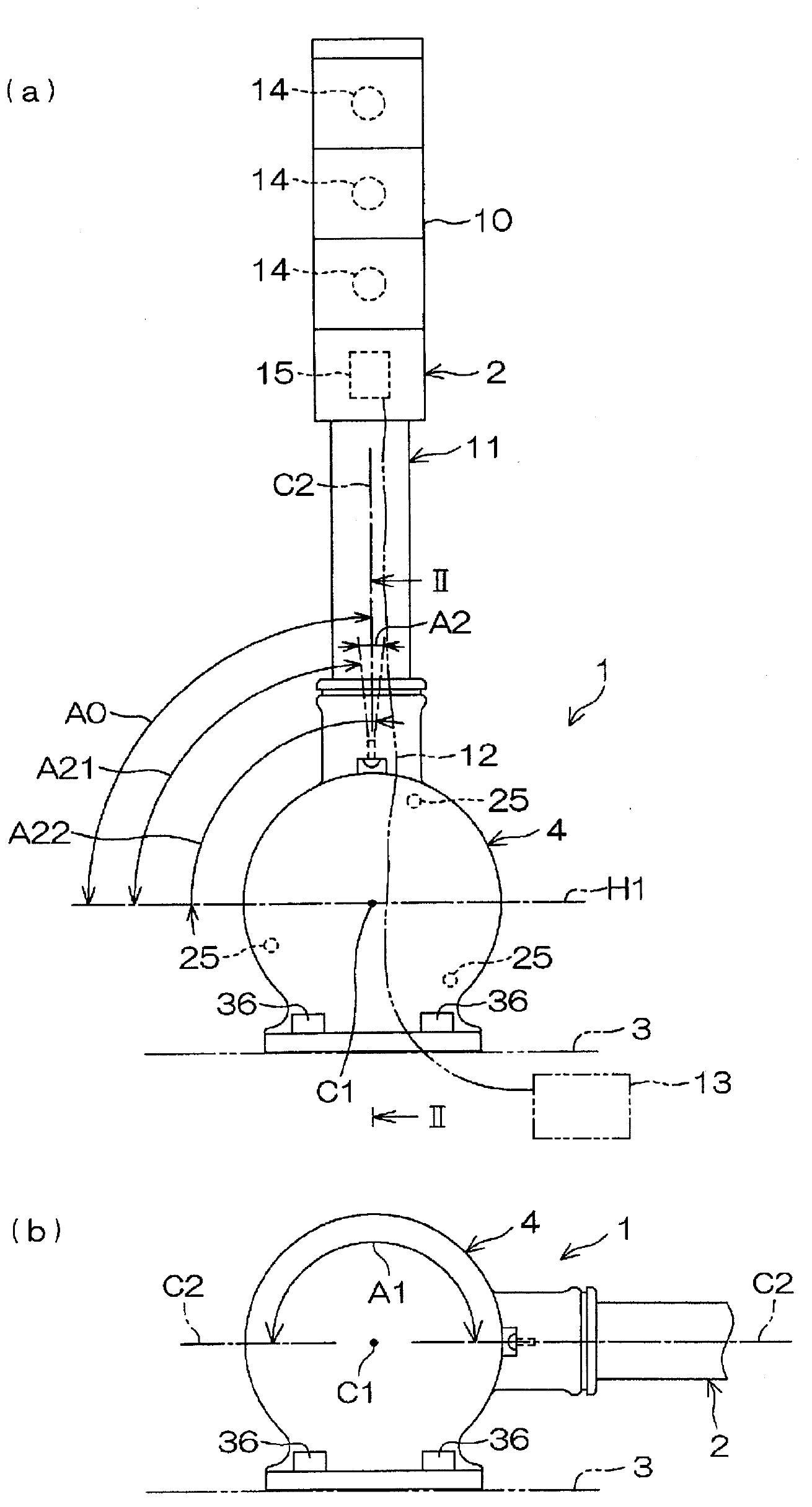
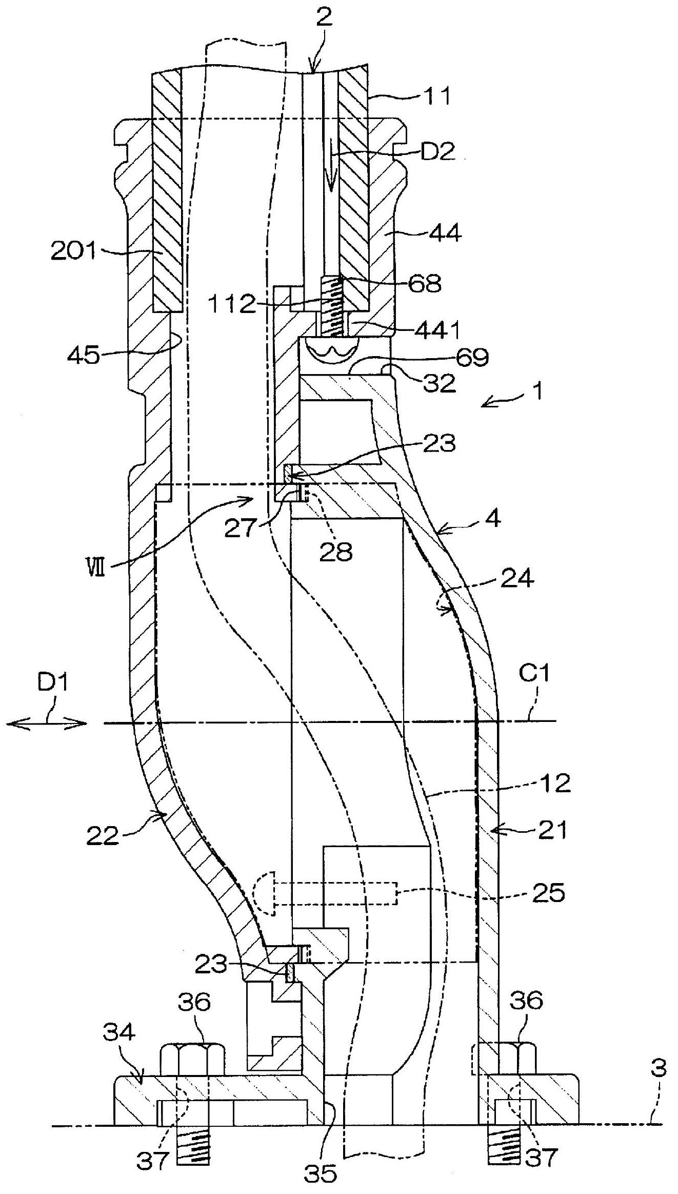
[0038] figure 1 (a) is a schematic diagram of a schematic structure of a signal display lamp unit including an angle fixing device according to an embodiment of the present invention, figure 1 (b) means to use figure 1 (a) Schematic diagram of the range in which the angle fixing device adjusts the installation angle of the signal display lamp. figure 2 Yes figure 1 (a) Cross-sectional view of II-II section. refer to figure 1 (a) The signal indicator lamp unit 1 has a signal indicator lamp 2 as a mounted device, and an angle fixing device 4 for attaching the signal indicator lamp 2 to a machine body 3 as an installation target so that the angle can be adjusted. The signal display lamp 2 emits light signals representing various information to the surroundings.

[0039] In this embodiment, the angle fixing device 4 will be described based on the signal dis...


PUM


Abstract

Disclosed is an angle setting device (4) having a first member (21) and a second member (22), which are coupled in a coupling direction (D1) parallel to a predetermined axis (C1), an annular seal (23) which defines a sealed space (24) between the first member (21) and the second member (22), and fastening members (25) which fasten the first member (21) with the second member (22) on the outer side of the annular seal (23) in the radial direction. The first member (21) is comprised of a first annular teeth row (27). The second member (22) is comprised of a second annular teeth row (28) which meshes with the first annular teeth row (27). The first annular teeth row (27) and the second annular teeth row (28) are annularly arranged about the predetermined axis (C1), and can be meshed at a predetermined rotational position in a circle about the predetermined axis (C1). The first annular teeth row (27) and the second annular teeth row (28) are arranged within the sealed space (24).

Description

technical field [0001] The present invention relates to an angle fixing device for fixing, for example, a signal indicator lamp, a lighting device, etc. in an adjustable manner. The present invention also relates to a signal display lamp unit and a lighting device unit comprising the above-mentioned angle fixing device. Background technique [0002] Signal indicator lamps are installed in automatic machines, production lines, parking lots, dangerous places, etc., and use the light emitted from the light source to signal various states such as material shortage, work jam, full parking, and danger. The signal display lamp unit has the above-mentioned signal display lamp and the above-mentioned angle fixing device for attaching the signal display lamp to an installation target, such as an automatic machine. [0003] The angle fixing device of Patent Document 1 has a first member fixed to a robot or the like, and a second member fixed to a signal indicator lamp. The first part...

Claims


Application Information

Patent Timeline
Patent Type & Authority Applications(China)
IPC IPC(8): F21V21/26F21S2/00
CPCF21V21/26F21V31/005F21W2111/00F21W2131/403
Inventor 清水博文上村佳子
Owner PATO RAITO KK
Why Eureka
Try Eureka