
Hole grinding fixture

A fixture and hole grinding technology, which is applied in the direction of grinding machines, manufacturing tools, grinding workpiece supports, etc., can solve the problems of the influence of the grinding machine spindle precision, long correction time, unstable quality, etc., and achieve the protection of grinding machine precision, grinding machine precision protection, saving The effect of correcting time

Inactive Publication Date: 2012-09-19
CHANGZHOU FEITIAN GEAR
View PDF12 Cites 0 Cited by
  • Summary
  • Abstract
  • Description
  • Claims
  • Application Information

AI Technical Summary

Problems solved by technology

In the process of development and trial production, the ordinary form of grinding fixtures is far from meeting the requirements of the product in terms of product accuracy and processing efficiency.
[0003] In the prior art, this type of grinding jig is generally tightened with a fixed core expansion sleeve and installed on a three-jaw chuck. However, this structure has the following disadvantages: (1) Each calibration takes a long time: according to product requirements, the internal The runout of the end surface and the cone surface is 0.015, and the cylindricity of the cone surface is less than 0.008. Therefore, the radial runout of the fixed core expansion sleeve of the grinding fixture is required to be less than 0.008. Due to the error of the three-jaw chuck itself and the manufacturing error of the fixture, the correction is very abnormal. Difficult, as long as about 2 hours; (2) Unstable quality and low production efficiency: Since each workpiece must be rotated and tightened with a wrench, the fixture is easy to move during the processing, and it is difficult for the operator to find it. I don't know when it moved. At this time, it is necessary to re-calibrate the fixture and re-check the quality of each workpiece in front. Therefore, on the one hand, it brings hidden dangers to the quality and makes the quality unstable. On the other hand, the production efficiency is low and the operation (3) Fixtures are easily damaged: During the calibration process, the three-jaw chuck is often knocked, which not only makes the chuck easily damaged, but also affects the spindle accuracy of the grinder; (4) Inconvenient to replace products: due to the There are many similar products, the batches are not large, and they need to be replaced frequently, so it brings difficulties to production arrangements

Method used


Image

  • Hole grinding fixture
  • Hole grinding fixture

Examples


Embodiment Construction

[0015] The preferred embodiments of the present invention will be described in detail below with reference to the accompanying drawings, so that the advantages and features of the present invention can be more easily understood by those skilled in the art, so as to make a clearer and clearer definition of the protection scope of the present invention.

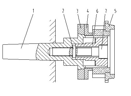
[0016] See figure 1 , The embodiment of the present invention includes:

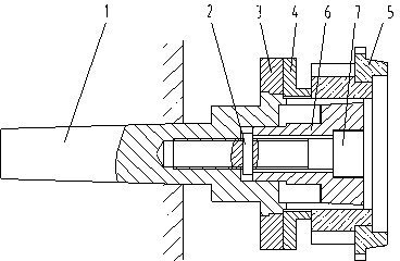
[0017] A hole grinding fixture, comprising an expanding core 6 and a Morse taper shank 1. The expanding core 6 is a taper expanding core, and the expanding core 6 is sleeved on one end of the grinding machine spindle 7, and the Morse taper shank 1 is connected to the grinding machine spindle 7 The inner taper hole is matched, and an anti-return pin 2 is provided between the expansion core 6 and the Morse taper handle 1.

[0018] A positioning block 4 is provided between the Morse taper shank 1 and the main body 5 of the grinder. The Morse taper shank 1 is fixed...


PUM


Abstract

The invention discloses a hole grinding fixture, which comprises an expansion core and a Mohs hardness handle, wherein the expansion core is a taper expansion core, the expansion core is sheathed on one end of a grinder spindle, the Mohs hardness handle is matched with an inner taper hole of the grinder spindle, and a backstop pin is arranged between the expansion core and the Mohs hardness handle. The hole grinding fixture, provided by the invention, has the advantages of being short in correction time, saving a large amount of correction time, being sable in quality, high in production efficiency, firm in the fixture, protecting precision of the grinder and saving the fixture.

Description

Technical field [0001] The invention relates to a hole grinding fixture. Background technique [0002] Gearbox gears on light trucks require grinding on both the inner end surface and the tapered surface, and the axial size of the inner end surface, the axial position of the tapered surface and the runout requirements are quite high. In the process of development and trial production, ordinary grinding fixtures are far from being able to meet product requirements in terms of product accuracy and processing efficiency. [0003] In the prior art, this type of grinding fixture is generally tightened with a fixed core expansion sleeve and mounted on a three-jaw chuck. However, this structure has the following shortcomings: (1) Each correction takes a long time: according to product requirements, The runout of the end surface and the tapered surface is 0.015, and the cylindricity of the tapered surface is less than 0.008. Therefore, it is required that the radial jump of the fixed core...

Claims


Application Information

Patent Timeline
IPC IPC(8): B24B5/35B24B41/06
Inventor 吴言发李迪郁文伟
Owner CHANGZHOU FEITIAN GEAR
Learn More