Compression-shear compound elastic wheel for rail vehicles

A rail transit vehicle and elastic wheel technology, which is applied in the field of compression-shear composite elastic wheels for rail transit vehicles, can solve the problems of low loading and unloading efficiency, increased processing procedures, hidden safety hazards, etc., achieve convenient assembly and disassembly operations, and improve use Safety, safe and reliable effect

Active Publication Date: 2012-09-19
CRRC CHANGZHOU TECH MARK IND CO LTD +1
View PDF8 Cites 11 Cited by
  • Summary
  • Abstract
  • Description
  • Claims
  • Application Information

AI Technical Summary

Problems solved by technology

[0003] The pressure ring and the wheel center of the current compression-shear composite elastic wheel are made of fasteners consisting of multiple bolts and nuts, which connect and fix the pressure ring and the wheel center. Due to the high pressure required for wheel assembly, the installation and disassembly process is relatively complicated. , so in the maintenance of elastic wheels, the loading and unloading efficiency is not high, and it also requires high strength and fatigue performance of fasteners
Secondly, the pressure roller and the wheel center are connected by bolts and nuts. When the bolts break, accidents will occur. Therefore, this connection structure also has certain safety hazards.
Moreover, the connection structure of bolts and nuts is adopted, and special bolt and nut connection parts need to be reserved when designing the elastic wheel, which occupies a certain installation space and increases the processing process, so it brings many difficulties to the elastic wheel with small wheel diameter.

Method used


Image

  • Compression-shear compound elastic wheel for rail vehicles
  • Compression-shear compound elastic wheel for rail vehicles
  • Compression-shear compound elastic wheel for rail vehicles

Examples


Embodiment Construction

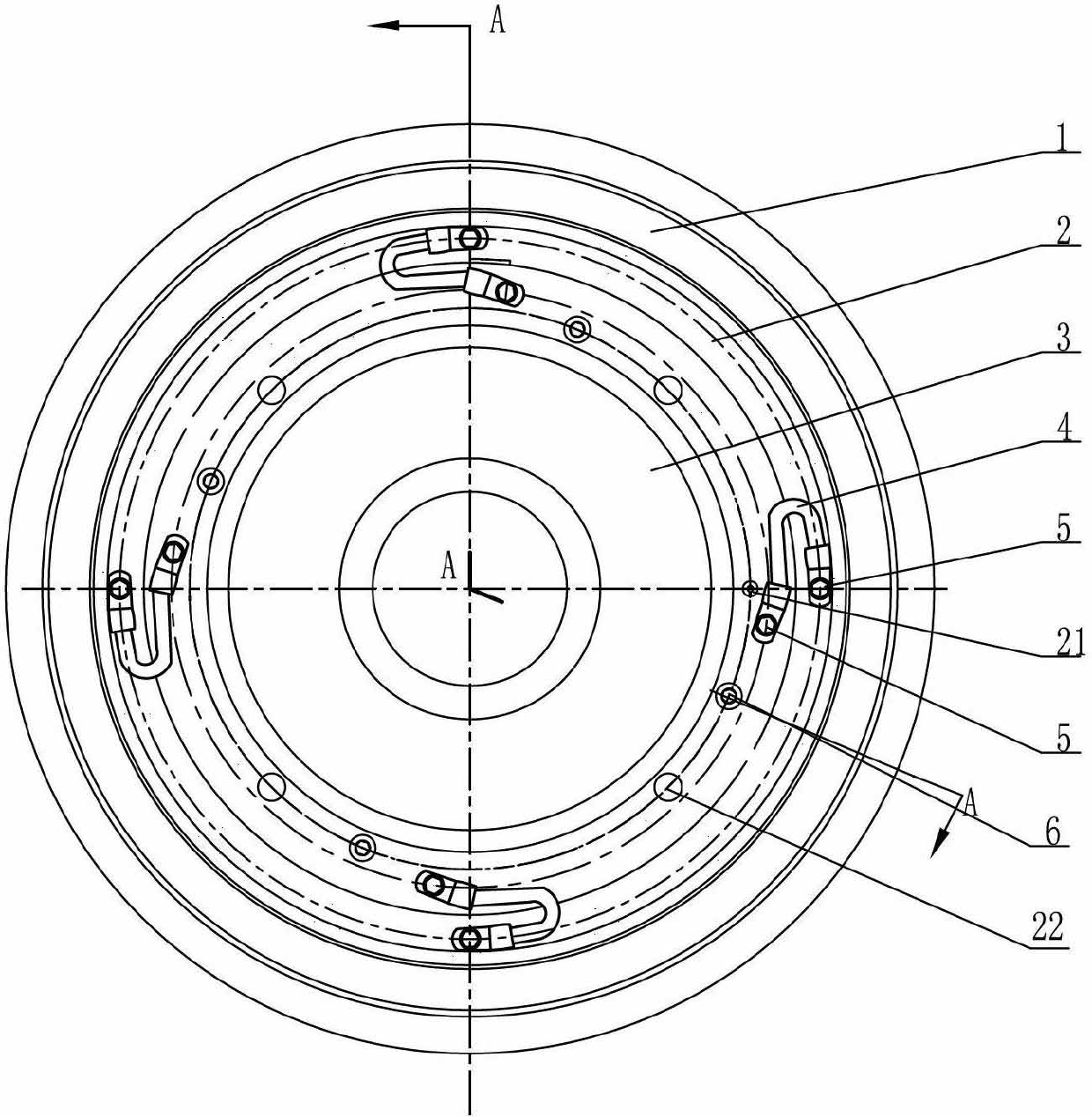
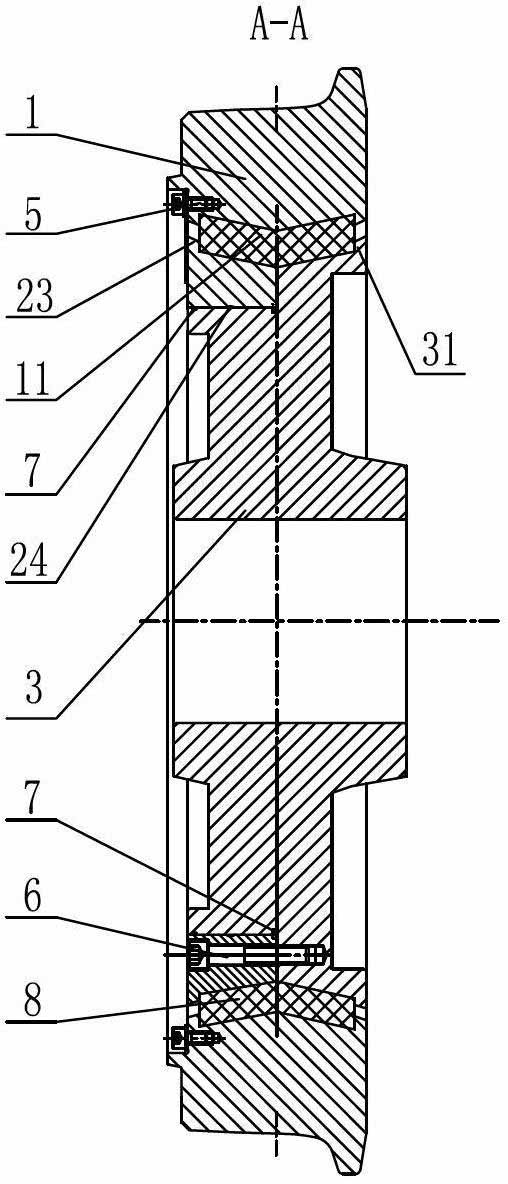
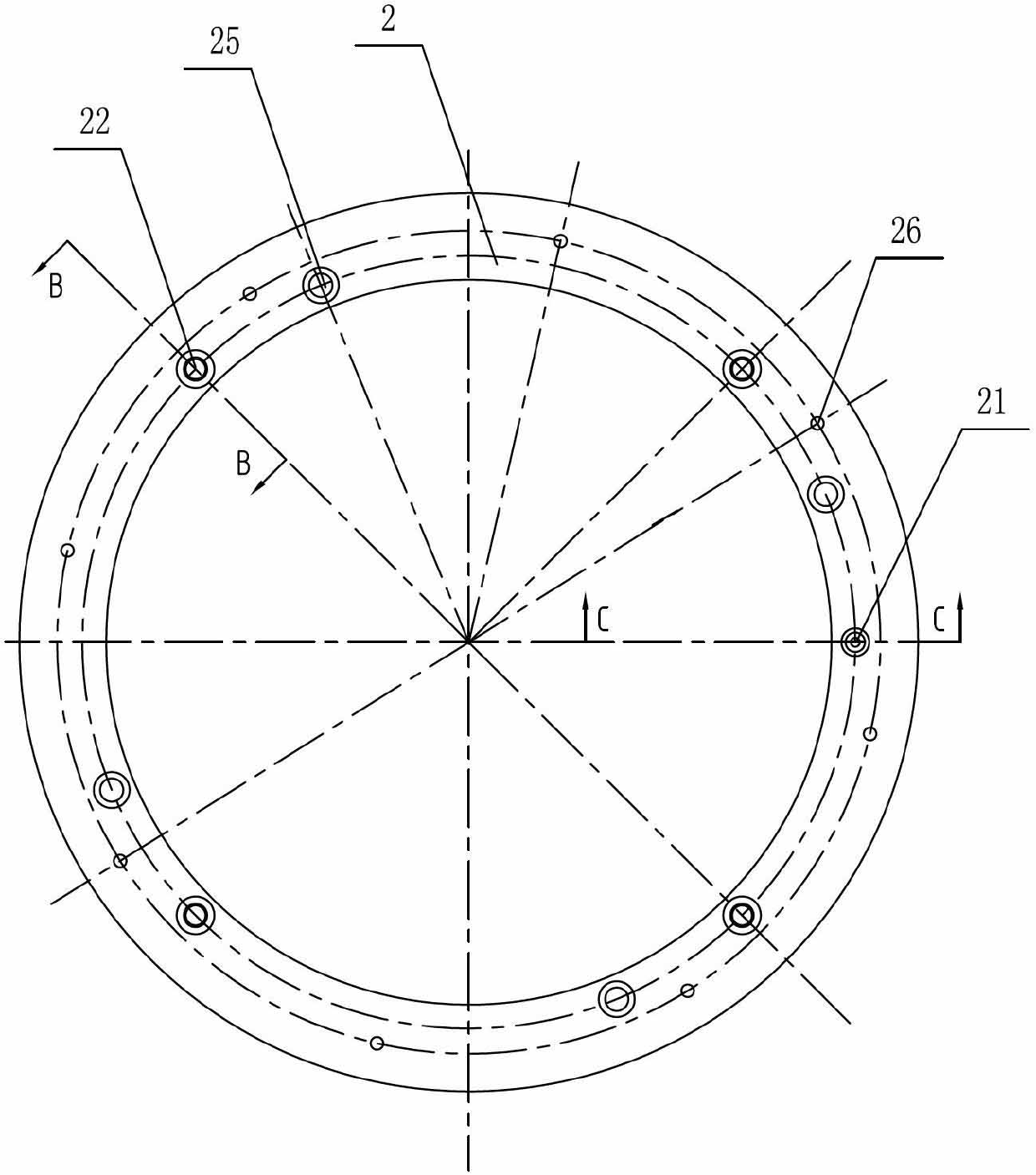
[0014] See Figure 1-5 As shown, the compression-shear composite elastic wheel for rail transit vehicles of the present invention comprises a tire 1, a wheel center 3, a pressure ring 2 and a V-shaped elastic element 8, and more than two elastic elements 8 are arranged between the tire 1 and the Between the wheel center 3 and the tire 1 and the pressure ring 2, and the two ends of the elastic element 8 are respectively connected to the two ends of the ring groove 11 of the tire 1 and the shoulder 23 on the pressure ring 2 and the shoulder 31 on the wheel center 3 The connection can prevent the wheel from derailing when the elastic element 8 fails, so as to improve the driving safety performance of the wheel. The elastic element 8 of the present invention is composed of 2 to 40 V-shaped rubber blocks. The elastic element 8 is made of rubber material, or the elastic element 8 is made of rubber material with a metal skeleton inside, or the elastic element 8 is equipped with Made...


PUM


Abstract

The invention relates to a compression-shear compound elastic wheel for rail vehicles. The elastic wheel comprises a hub, a wheel center, a compression ring and V-shaped elastic elements. More than two elastic elements are arranged among the hub, the wheel center and the compression ring, two ends of the elastic elements are respectively connected with two end faces of a hub ring groove and beadings on the compression ring and the wheel center, the compression ring is mounted on the wheel center in a press assembling mode, more than three threaded holes are distributed evenly along the circumference of the compression ring, more than three threaded holes are arranged correspondingly in the wheel center, and more than three connection fastening pieced are connected onto the threaded holes in the compression ring and the wheel center in a rotary mode; more than two jacking threaded holes for mounting jacking bolts are arranged on the compression ring, an annular oil groove is mounted on an inner hole wall of the compression ring and communicated with an oil filling hole in an end face of the compression ring, and sealing rings are mounted on two sides of the annular oil groove of the wheel center on the inner wall of the compression ring. The compression-shear compound elastic wheel for rail vehicles has the advantages of being reasonable in structure, capable of improving security performances, and convenient to mount and dismount and maintain.

Description

technical field [0001] The invention relates to a compression-shear composite elastic wheel for rail transit vehicles, belonging to the technical field of elastic wheels for light rail vehicles. Background technique [0002] With the rapid development of urban rail transit subways and light rails, more and more rail transit vehicles use elastic wheels with shear-compression rubber components. A certain oblique angle, under the action of vertical load, is both sheared and compressed. In the application, as long as the installation slope and thickness of the rubber pad are properly changed, its radial and axial cushioning properties can be adjusted. Due to the use of elastic wheels, the weight of the unsprung part of the vehicle can be significantly reduced, the force between the wheel and the rail can be reduced, the impact can be eased, the stability of the vehicle can be improved, and the operating conditions of the wheels and axles can be improved. [0003] The pressure ...

Claims


Application Information

Patent Timeline
Patent Type & Authority Applications(China)
IPC IPC(8): B60B17/02
CPCB60B17/0044
Inventor 戚援韩啸郭晓晖郑志立
Owner CRRC CHANGZHOU TECH MARK IND CO LTD
Why Eureka
Try Eureka