Dragging-saw grooving machine without sticking drill

A stick-drill saw-saw-type slotting machine technology, which is applied in the directions of earthmoving machines/shovels, construction, etc., can solve the problems of unusability and low slotting efficiency of saw-saw slotting machines.

Active Publication Date: 2012-09-19
中阳建设集团有限公司
View PDF6 Cites 4 Cited by
  • Summary
  • Abstract
  • Description
  • Claims
  • Application Information

AI Technical Summary

Problems solved by technology

[0002] At present, the saw-type grooving machine used in the construction of underground anti-seepage walls, because the soil is attached between the teeth and moves with the teeth during the grooving process, so the grooving efficiency of the saw-type grooving machine is very low and cannot be used in viscous soil

Method used


Image

  • Dragging-saw grooving machine without sticking drill
  • Dragging-saw grooving machine without sticking drill
  • Dragging-saw grooving machine without sticking drill

Examples


Embodiment Construction

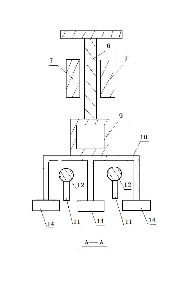
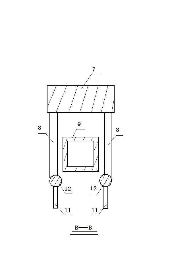
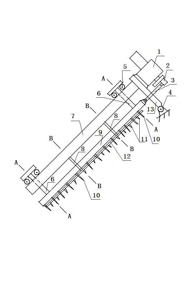
[0013] Accompanying drawing is a kind of specific embodiment of the present invention, and this embodiment speed reducer 1 is fixed on the right end of vertical arm 13, and the lower end of speed reducer is provided with crank 2, and crank is hinged on the right end of support arm 9 by connecting rod 3, and vertical arm 13 The left end of the support arm A7 is fixed, the lower ends of the two pull rods 6 are fixed on the support rod B9, the upper end of the pull rod is hung on the support arm A7 through two rollers 5, and the lower part of the support rod B is provided with two support rods C12, each support rod C is fixed on the support arm A through two connecting rods 8. The lower end of the support rod C is provided with a plurality of cutter teeth B11, and the lower end of the support rod B is provided with a plurality of cutter teeth A10. A knife edge 14 is provided, and two support rods C12 pass through the knife teeth A10 of the inverted mountain structure.

[0014] Wh...


PUM


Abstract

The invention relates to a dragging-saw grooving machine without sticking a drill, which is used for grooving an underground diaphragm wall. A reducer is fixedly arranged at the right end of a vertical arm, and the lower end of the reducer is provided with a crank. The crank is hinged at the right end of a support arm through a connecting rod, and the left end of the vertical arm is fixedly arranged at the support arm A. The lower ends of two pull rods are fixedly arranged at a support rod B, and the upper ends of the pull rods are hung on the support arm A through two idler wheels. The lower part of the support rod B is provided with two support rods C, and each support rod C is fixedly arranged on the support arm A through two connecting rods. The lower ends of the support rods C are provided with a plurality of cutter teeth B, and the lower end of the support rod B is provided with a plurality of cutter teeth A. The cutter teeth A adopt a reverse hill substructure, and the lower ends of the cutter teeth A are provided with blades. The cutter teeth A of the grooving machine move back and forth, and the cutter teeth B do not move among the cutter teeth A, so that the cutter teeth A and the cutter teeth B form relative movement, and soil cut by the cutter teeth A is removed by the cutter teeth B. The grooving efficiency is high, and a soil body with large stickiness can also be grooved.

Description

1. Technical field [0001] The invention relates to a grooving machine, in particular to a non-stick drill and saw-type grooving machine for underground anti-seepage wall grooving. 2. Background technology: [0002] At present, the saw-type grooving machine used in the construction of underground anti-seepage walls, because the soil is attached between the teeth and moves with the teeth during the grooving process, so the grooving efficiency of the saw-type grooving machine is very low And it cannot be used in soil with high viscosity. 3. Contents of the invention: [0003] The invention makes up for the shortcomings of the above saw-type slotting machine, and provides a non-stick drill and saw-type slotting machine. [0004] The present invention is achieved through the following technical solutions: [0005] A non-stick drill saw-type slotting machine, the reducer is fixed on the right end of the vertical arm, the lower end of the reducer is provided with a crank, the c...

Claims


Application Information

Patent Timeline
Patent Type & Authority Applications(China)
IPC IPC(8): E02F5/02
Inventor 张永忠
Owner 中阳建设集团有限公司
Why Eureka
Try Eureka