
Vertical cementing manifold for offshore oil production

A vertical and offshore technology, applied in the direction of drilling pipes, casings, and mining fluids, etc., it can solve the problems of inconvenient operators, large number of manifold elbows, and large floor space, so as to achieve convenient operation and reduce occupation Ground area, the effect of reducing welding points

Inactive Publication Date: 2012-09-19
韦波
View PDF0 Cites 2 Cited by
  • Summary
  • Abstract
  • Description
  • Claims
  • Application Information

AI Technical Summary

Problems solved by technology

[0002] Offshore oilfield development sites are different from land, especially the wellhead equipment occupies a very small area. The original horizontal installation cementing manifold occupies a large area, and the number of manifold elbows is large, and there must be many welding points. There are many leakage points, and it is not very convenient for operators

Method used


Image

  • Vertical cementing manifold for offshore oil production

Examples


Embodiment Construction

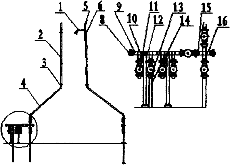
[0017] Such as figure 1 As shown, the vertical cementing manifold for offshore oil production includes straight pipe A1, straight pipe B2, 120° elbow 3, straight pipe C4, top support pipe 5, tee A6, union male A7, Nut 8, female union head 9, tee B10, plug valve 11, support assembly 12, male union head B13, straight pipe D14, extended union female head 15 and cross 16, in the cementing pipe body The lower part of the installation manifold.

[0018] In the vertical cementing manifold for offshore oil production of the present invention, a straight pipe A1 and a straight pipe B2 are installed on the upper part of the pipe body.

[0019] In the vertical cementing manifold for offshore oil production of the present invention, a 120° bend pipe 3 and a straight pipe C4 are installed in the middle of the pipe body.

[0020] In the vertical cementing manifold for offshore oil production of the present invention, a top support pipe 5 and a tee A6 are installed on the top of the pipe b...


PUM


Abstract

The invention discloses a vertical cementing manifold for offshore oil production. The vertical cementing manifold comprises a straight pipe A (1), a straight pipe B (2), a 120-degree elbow (3), a straight pipe C (4), a top support pipe (5), a tee joint A (6), a union male joint A (7), a union nut (8), a union female joint (9), a tee joint B (10), a plug valve (11), a support base assembly (12), a union male joint B (13), a straight pipe D (14), an elongated union female joint (15) and a four-way joint (16); and the manifold is installed on the lower part of the cementing pipe body. In the vertical cementing manifold for offshore oil production, the plug valve of the cementing manifold is assembled on a simple vertical pry seat, so that not only the floor area is reduced, but also the operation of field workers is facilitated, the use quantity of elbows is reduced, and the welding points and the leakage are decreased.

Description

technical field [0001] The invention relates to a cementing manifold, in particular to a vertical cementing manifold for marine oil production. Background technique [0002] Offshore oilfield development sites are different from land, especially the wellhead equipment occupies a very small area. The original horizontal installation cementing manifold occupies a large area, and the number of manifold elbows is large, and there must be many welding points. There are many leakage points, and it is not very convenient for operators. Contents of the invention [0003] The purpose of the present invention is to provide a vertical cementing manifold for offshore oil production, and fix the cementing manifold cock valve group on a simple vertical skid seat, which not only reduces the occupied area, but also facilitates the on-site personnel operation, reducing the number of elbows used, reducing welding points, and reducing leakage. [0004] The technical solution of the present...

Claims


Application Information

Patent Timeline
IPC IPC(8): E21B43/01E21B17/00E21B34/04
Inventor 韦波
Owner 韦波
Learn More