A pump body cooling circulation system of a rotary compressor

A rotor compressor and circulation system technology, applied in the field of compressors, can solve problems such as heat removal, and achieve the effects of improving efficiency, reducing exhaust temperature and suction superheat

Active Publication Date: 2016-03-02
SHANGHAI HITACHI ELECTRICAL APPLIANCES CO LTD
View PDF7 Cites 0 Cited by
  • Summary
  • Abstract
  • Description
  • Claims
  • Application Information

AI Technical Summary

Problems solved by technology

But how to take away the heat generated by the gas has not yet been reported

Method used


Image

  • A pump body cooling circulation system of a rotary compressor
  • A pump body cooling circulation system of a rotary compressor
  • A pump body cooling circulation system of a rotary compressor

Examples


Embodiment 1

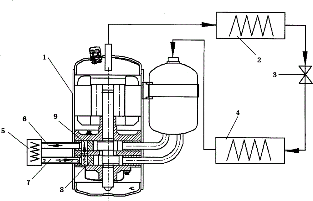
[0021] Such as Figure 2-5 As shown, an air conditioning cycle system includes a compressor 1, a first condenser 2, an expansion valve 3 and an evaporator 4, and the exhaust port of the compressor 1 is connected to the first condenser 2, the expansion valve 3 and the evaporator in sequence. The evaporator 4 is connected to the suction port of the compressor 1.

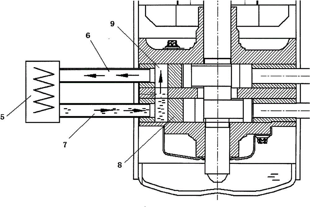
[0022] The above-mentioned compressor 1 is additionally provided with a pump body cooling circulation system, which is arranged on the pump body of the compressor, including a second condenser 5, an exhaust pipe 6 and a liquid inlet pipe 7, and the pump body includes an upper cylinder head, a cylinder and The lower cylinder head is provided with a closed cavity 9 on the cylinder 8, and the structure of the closed cavity 9 opened on the cylinder is as follows: Figure 4-5 shown. Two pipes are respectively connected up and down in the airtight cavity 9, and the compressor casing is led out to connect with the second co...


PUM


Abstract

The invention provides a cooling circulation system of a rotor compressor pump body which comprises a pump body, an exhausting pipe, a liquid inlet pipe and a condenser, wherein an airtight cavity is arranged on the pump body, the upper end of the airtight cavity is connected with the condenser through the exhausting pipe, and the lower end of the airtight cavity is connected with the condenser through the liquid inlet pipe. Compared with the prior art, the cooling circulation system can cool the pump body in a casing, transmits the heat generated in the air compressing process to the external environment of the compressor, accordingly reduces the temperature of exhausted air and air suction degree of superheat and improves efficiency of the compressor.

Description

technical field [0001] The invention relates to a compressor, in particular to a cooling circulation system for a pump body of a rotor compressor. Background technique [0002] The shell of the high back pressure rotary compressor is the high temperature and high pressure gas discharged by the compressor. The pump body in the shell is surrounded by the high temperature and high pressure gas, and the material of the pump body is generally cast iron, which has a strong thermal conductivity, and the heat in the shell will Gas passed to the suction and compression process, thereby reducing the efficiency of the compressor. For low-backpressure rotary compressors, the housing contains low-temperature and low-pressure gas. After the heat generated by the compressor is absorbed by the gas in the housing, it will increase the superheat of the suction gas, thereby reducing the performance of the system. [0003] In order to reduce the performance loss caused by the heat transfer of ...

Claims


Application Information

Patent Timeline
Patent Type & Authority Patents(China)
IPC IPC(8): F04C29/04
Inventor 张海锋谢飞王硕渊
Owner SHANGHAI HITACHI ELECTRICAL APPLIANCES CO LTD
Why Eureka
Try Eureka