Water tank (with nozzle pipe) of solar water heater

A technology for solar water heaters and water tanks, which is applied in the field of solar heat utilization, and can solve problems such as low heat conduction medium, low heat conduction efficiency, and viscous heat conduction medium

Inactive Publication Date: 2012-09-19
ZHENJIANG XINMENGXI ENERGY TECH
View PDF9 Cites 11 Cited by
  • Summary
  • Abstract
  • Description
  • Claims
  • Application Information

AI Technical Summary

Problems solved by technology

Flat-panel solar water heaters mostly use indirect heating, and the heat conduction medium is relatively viscous, resulting in low heat conduction efficiency
[0003] At present, there are many patents on solar water heater tanks, but a tank that can use a heat transfer medium with a relatively low boiling point and install a nozzle to accelerate the flow of the medium has not yet been found.

Method used


Image

  • Water tank (with nozzle pipe) of solar water heater
  • Water tank (with nozzle pipe) of solar water heater

Examples


Embodiment Construction

[0010] The embodiments of the present invention will be further described below in conjunction with the accompanying drawings.

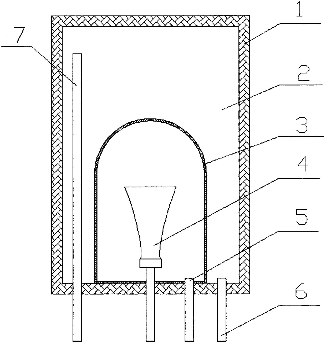
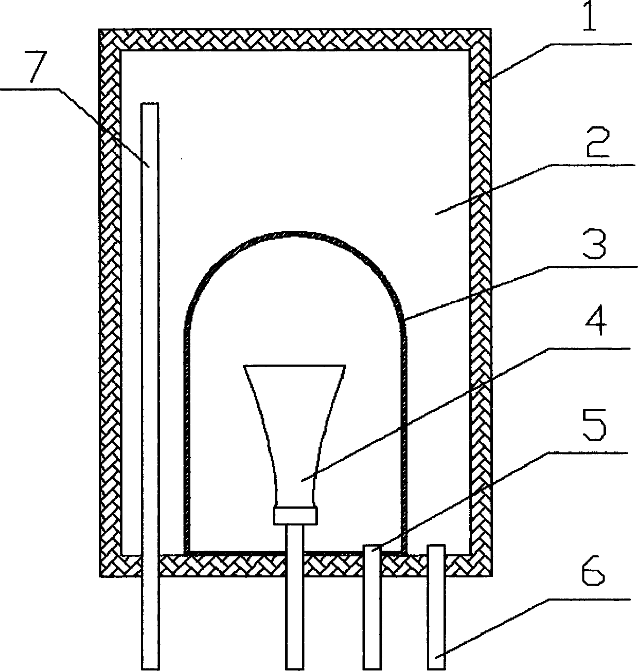
[0011] The solar water heater water tank is connected with a solar heat collector outside, and the inside of the heating liner 3 is filled with a heat conduction medium, and the heat conduction medium flows into the solar heat collector from the liquid outlet 5 to absorb heat and vaporize. The vaporized heat transfer medium enters the heating inner tank 3 from the liquid inlet nozzle 4 . When passing through the liquid inlet nozzle 4, the flow rate of the medium rises. The medium flow impinges on the thin wall of the heating liner, stagnation occurs, the temperature further increases, and the heat is condensed on the thin wall. The condensed heat transfer medium collects at the bottom of the heating liner 3 and flows back from the liquid outlet 5 .


PUM


Abstract

The invention discloses a water tank (with a nozzle pipe) of a solar water heater, A heating bladder is arranged in the water tank, and a fed-fluid nozzle pipe is arranged in the heating bladder, so that the speed of a gaseous heat-conducting medium flow can be improved. The heat-conducting medium flow hits against the wall of the heating bladder, so that a stagnation phenomenon occurs, and an effect of further warming is achieved, thereby accelerating the heat exchange of domestic water in the heating bladder and the water tank.

Description

technical field [0001] The invention relates to solar heat utilization technology, in particular to a solar water heater water tank in which a nozzle is installed at a liquid inlet nozzle inside a heating liner of the water tank. Background technique [0002] In the field of solar thermal utilization, solar water heaters have appeared in a variety of mature products including vacuum tube water heaters and flat plate water heaters. Flat plate solar water heaters are rapidly opening up the market due to their longer service life and easy installation methods. Flat-panel solar water heaters mostly use indirect heating, and the heat conduction medium is relatively viscous, resulting in low heat conduction efficiency. [0003] Existing multiple patents about the solar water heater water tank at present, but can use the relatively low thermal conduction medium of boiling point, and the water tank that installs nozzle to accelerate medium flow has not been found yet. A few existin...

Claims


Application Information

Patent Timeline
Patent Type & Authority Applications(China)
IPC IPC(8): F24J2/46
CPCY02E10/40
Inventor 王金平
Owner ZHENJIANG XINMENGXI ENERGY TECH
Why Eureka
Try Eureka