Method for calibrating strain parameters of optical fiber sensor and optical fiber grating

A fiber optic sensor and fiber grating technology, which is applied to instruments, optical devices, measuring devices, etc., can solve the problems of narrow measurement range, low measurement accuracy, and difficulty in meeting measurement requirements.

Active Publication Date: 2012-09-19
THE 41ST INST OF CHINA ELECTRONICS TECH GRP
View PDF7 Cites 14 Cited by
  • Summary
  • Abstract
  • Description
  • Claims
  • Application Information

AI Technical Summary

Problems solved by technology

[0008] The elastic modulus method and the equal-intensity cantilever beam method are commonly used methods in the measurement of resistance strain gauge sensors. Among them, the elastic modulus method is widely used in engineering, but the measurement accuracy is not high. The equal-intensity cantilever beam me

Method used


Image

  • Method for calibrating strain parameters of optical fiber sensor and optical fiber grating
  • Method for calibrating strain parameters of optical fiber sensor and optical fiber grating
  • Method for calibrating strain parameters of optical fiber sensor and optical fiber grating

Examples


Embodiment Construction

[0019] The preferred embodiments of the present invention will be described in detail below in conjunction with the accompanying drawings; it should be understood that the preferred embodiments are only for illustrating the present invention, rather than limiting the protection scope of the present invention.

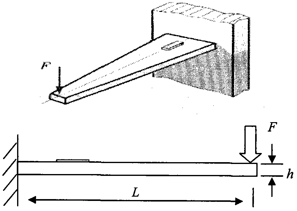
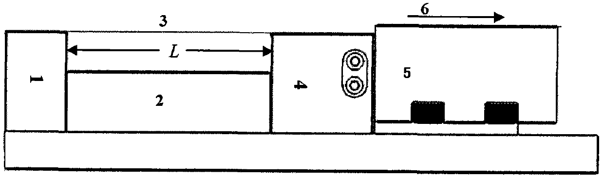
[0020] The method adopts a displacement measurement method, and combines a precision displacement sensor and an optical fiber sensor to produce a standard transmission part to generate a standard strain value, thereby indirectly achieving the calibration of the optical fiber sensor and the optical fiber grating strain parameters. Optical fiber strain transmission parts mainly include "concave" optical bracket 2, standard optical fiber sensor 3, precision displacement sensor 5, displacement sensor controller, etc. The "concave" shaped optical bracket 2 is composed of an optical slide rail guide groove, a fixed end 1 and a free end 4. There are "V" grooves engraved on the...


PUM


Abstract

The invention discloses a method for calibrating strain parameters of an optical fiber sensor and an optical fiber grating. A standard strain value is generated by a standard transmission piece which is manufactured by a mode of combining a precise displacement sensor and the optical fiber sensor through using a displacement measurement method, so that the strain parameters of the optical fiber sensor and the optical fiber grating can be calibrated indirectly. The method is characterized in that the standard transmission piece comprises a concave optical bracket, the standard optical fiber sensor, the precise displacement sensor and a displacement sensor controller, wherein the concave optical bracket consists of an optical sliding rail guide slot, a fixed end and a free end; V-shaped slots are engraved above the free end and the fixed end; and a base and a sliding rail of the displacement sensor are fixed by bolts, connected with the free end of the optical bracket in the transverse direction and then connected with the displacement sensor controller through data lines.

Description

technical field [0001] The invention relates to a method for calibrating strain parameters of an optical fiber sensor and an optical fiber grating. Background technique [0002] Optical fiber sensors based on Brillouin scattering (fiber optic gyro fiber ring) and strain sensors based on fiber Bragg gratings (FBG) are widely used in the fields of attitude control, precise guidance of aerospace devices, and health detection of large bridge buildings. Relate the Brillouin scattering coefficient, the wavelength shift and the strain on the fiber. These methods have disadvantages such as expensive instruments and difficulty in traceability. Most of the existing calibration test methods use comparative measurement, and the test accuracy is difficult to guarantee. The stress distribution and quality inside the fiber optic ring directly affect the accuracy and stability of the fiber optic gyroscope, which is an important factor restricting the current domestic high-precision fiber ...

Claims


Application Information

Patent Timeline
IPC IPC(8): G01B11/16
Inventor 韩正英郑光金高业胜赵耀纪宝平
Owner THE 41ST INST OF CHINA ELECTRONICS TECH GRP
Why Eureka
Try Eureka