A Temporary Aligner for Ribbon Optical Fiber

A ribbon optical fiber and aligner technology, which is applied in the coupling of optical waveguides, can solve the problems of complex and cumbersome fusion splicing operations, material consumption, etc., and achieve the effects of improving work efficiency and simplifying temporary docking operations

Active Publication Date: 2014-10-29
BENGBU JIXIN COMM MACHINERY
View PDF7 Cites 0 Cited by
  • Summary
  • Abstract
  • Description
  • Claims
  • Application Information

AI Technical Summary

Problems solved by technology

[0004] The purpose of the present invention is to provide a temporary optical fiber aligner in order to solve the problems in the prior art that the optical fiber fusion splicing operation is complicated and tedious and consumes materials when the optical fibers need to be temporarily connected.

Method used


Image

  • A Temporary Aligner for Ribbon Optical Fiber
  • A Temporary Aligner for Ribbon Optical Fiber

Examples


Embodiment Construction

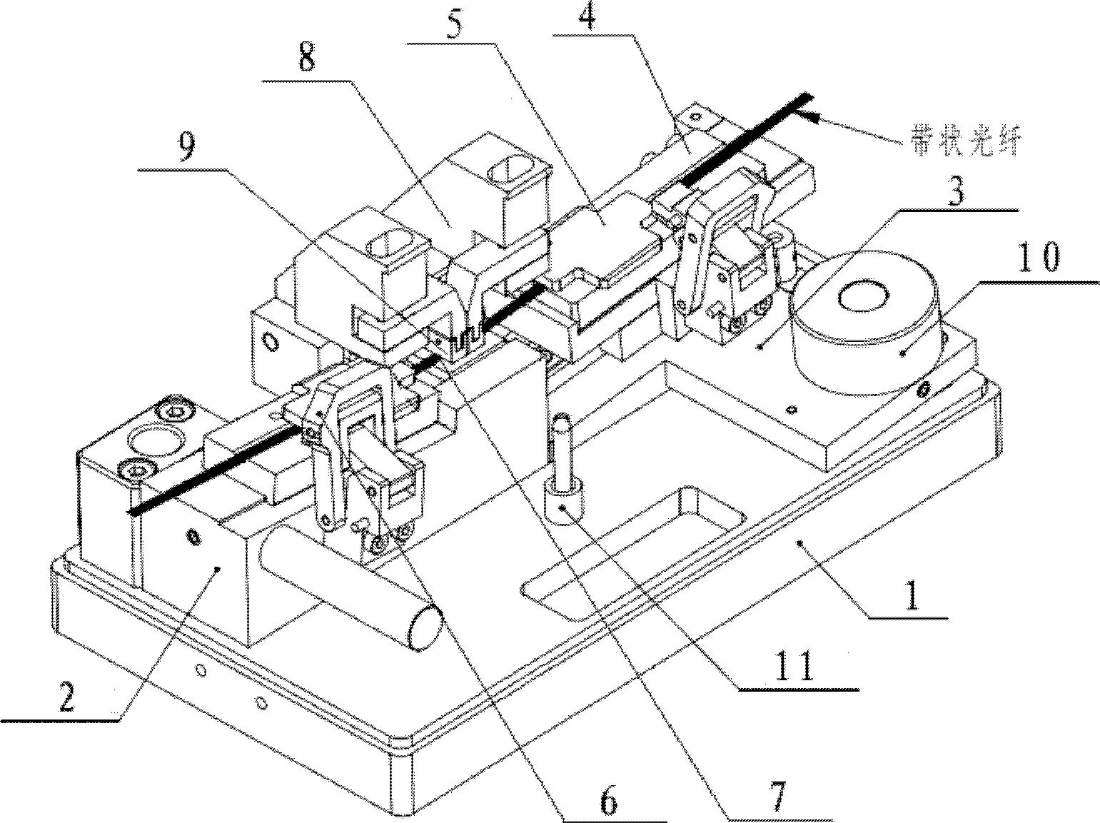
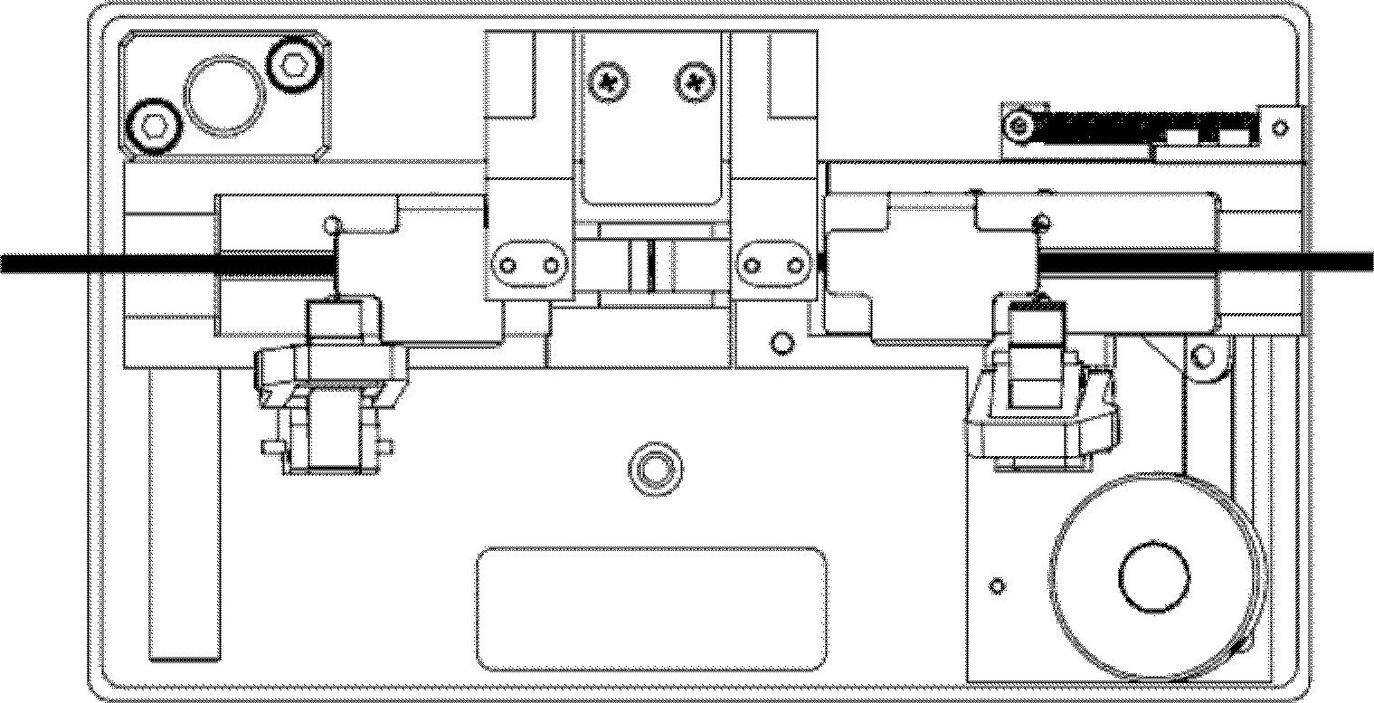
[0017] like figure 1 As shown, a ribbon-shaped optical fiber temporary aligner includes a base 1, a left fixture seat 2 is fixedly installed on the base 1, a right fixture seat 3 is slidably installed, and a left fixture seat 2 and a right fixture seat 3 are respectively installed with The bottom plate 4 and the pressure block 5 are attracted to each other, and the chucks 6 are respectively hinged to clamp the bottom plate 4 and the pressure block 5. The right end of the left clamp seat 2 is equipped with a V-groove 7 that cooperates with the ribbon-shaped bare fiber. The left clamp seat 2 is also hinged with a pressure head 8 for pressing on the V groove 7, and the right clamp seat 3 can make the bare fiber part of the ribbon optical fiber clamped on it extend into the V groove 7 through a sliding operation, and connect with the left Ribbon fiber alignment in holder 2.

[0018] Both the left fixture seat 2 and the right fixture seat 3 are provided with guide bosses, the ...


PUM


Abstract

The invention discloses a temporary aligner of a ribbon optical fiber. The aligner comprises a base, wherein a left fixture seat is installed fixedly on the base, a right fixture seat is installed on the base in a sliding mode, a V-shaped groove which is matched with a bare fiber of the ribbon optical fiber is installed at the right end of the left fixture seat, a pressing head which is used for pressing the V-shaped groove is hinged on the left fixture seat, and the right fixture seat can enable a bare fiber portion of the ribbon optical fiber which is clamped on the right fixture to extend into the V-shaped groove and enable the bare fiber portion to be aligned to the ribbon optical fiber in the left fixture seat through sliding operation. According to the requirement for temporary optical fiber butt joint, the device can achieve rapid butt joint of two optical fibers; however, traditional fusion splicers are complex in operation. The temporary aligner simplifies temporary butt joint operation, improves working efficiency and is applicable to ribbon optical fibers and monomode optical fibers. During usage, optical fiber materials are not consumed, welding effects after butt joint are achieved basically, and temporary experimental butt joint requirements are met.

Description

technical field [0001] The invention relates to an optical fiber connection device, in particular to a ribbon-shaped optical fiber temporary aligner. Background technique [0002] Optical fiber is a light transmission tool that utilizes the principle of total reflection of light in fibers made of glass or plastic, and has a wide range of applications in the field of communication. During the construction and maintenance of optical fiber laying, it is often necessary to perform fusion splicing operations on optical fibers, so optical fiber fusion splicers are indispensable equipment for optical communication engineering. The fusion splicing operation of the optical fiber is mainly to melt the two optical fibers by emitting an arc, and at the same time use the collimation principle to advance gently to realize the coupling of the optical fiber mode field. [0003] In the actual use of optical fibers, sometimes it is only necessary to temporarily connect the optical fibers...

Claims


Application Information

Patent Timeline
Patent Type & Authority Patents(China)
IPC IPC(8): G02B6/38G02B6/36
Inventor 田林云张超
Owner BENGBU JIXIN COMM MACHINERY
Why Eureka
Try Eureka