Reactor and power converter using the same

A technology of reactance and summation, applied in the field of power conversion devices, can solve the problems of reactance device loss, Joule heat, etc., and achieve the effect of suppressing losses

Inactive Publication Date: 2012-09-19
HITACHI LTD
View PDF5 Cites 8 Cited by
  • Summary
  • Abstract
  • Description
  • Claims
  • Application Information

AI Technical Summary

Problems solved by technology

In this case, there is a problem that heat called Joule heat is generated, causing loss in the reactance device

Method used


Image

  • Reactor and power converter using the same
  • Reactor and power converter using the same
  • Reactor and power converter using the same

Examples


Embodiment approach 1

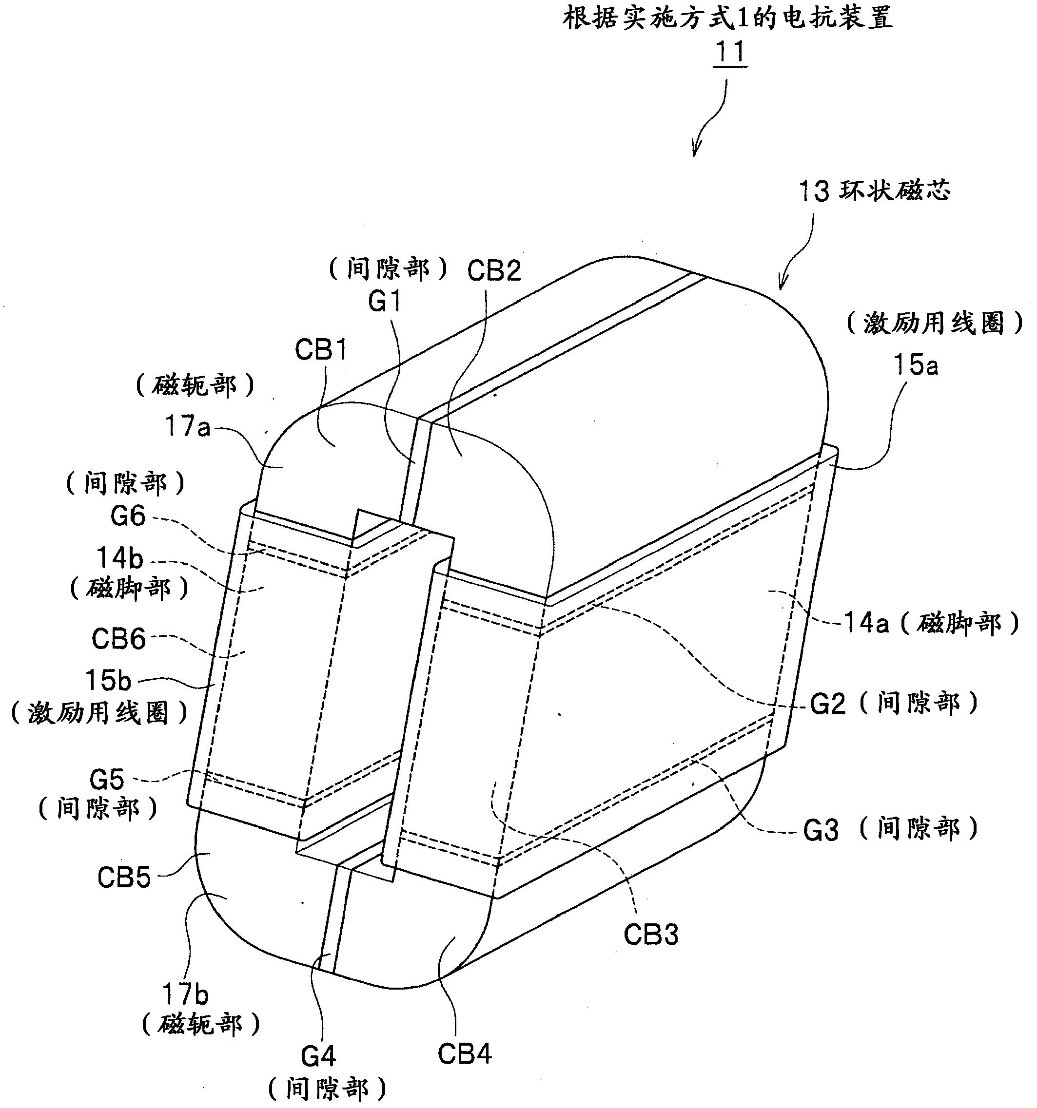
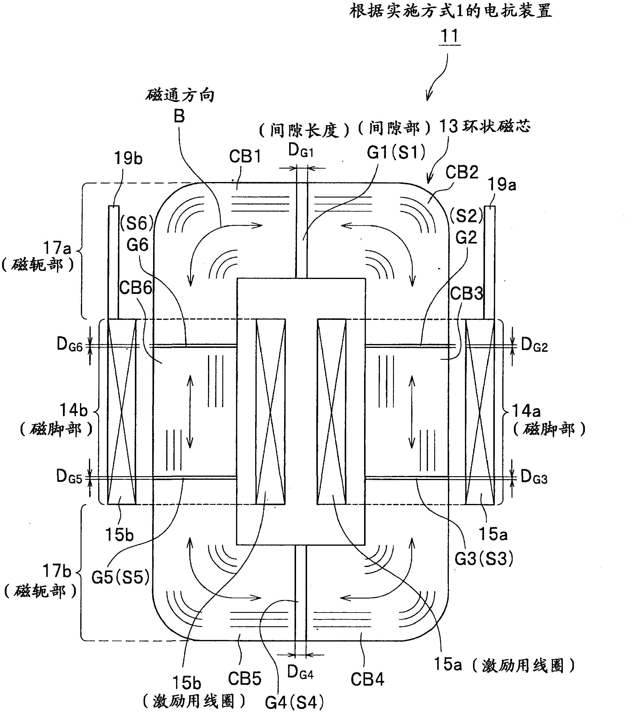
[0025] Figure 1A is an overall perspective view of the reactance device according to Embodiment 1 of the present invention. Figure 1B is a front cross-sectional view of the reactor according to Embodiment 1 of the present invention. exist Figure 1A and Figure 1B In, for example, the term "(magnetic leg)" in parentheses after the reference numeral 14a indicates that the component of the reference numeral 14a, that is, the "first magnetic leg 14a" is the same as the term "magnetic leg" in the claims. correspond. As for other components other than the reference numeral 14a, the above-mentioned notation method is also followed. in addition, Figure 1A and Figure 1B Other drawings other than , also follow the above-mentioned marking method.

[0026] According to the reactance device 11 according to Embodiment 1 of the present invention, even when there are gaps G2, G3, G5, and G6 in the region of the annular core 13 around which the excitation coil 15 is wound, the magneti...

Embodiment approach 2

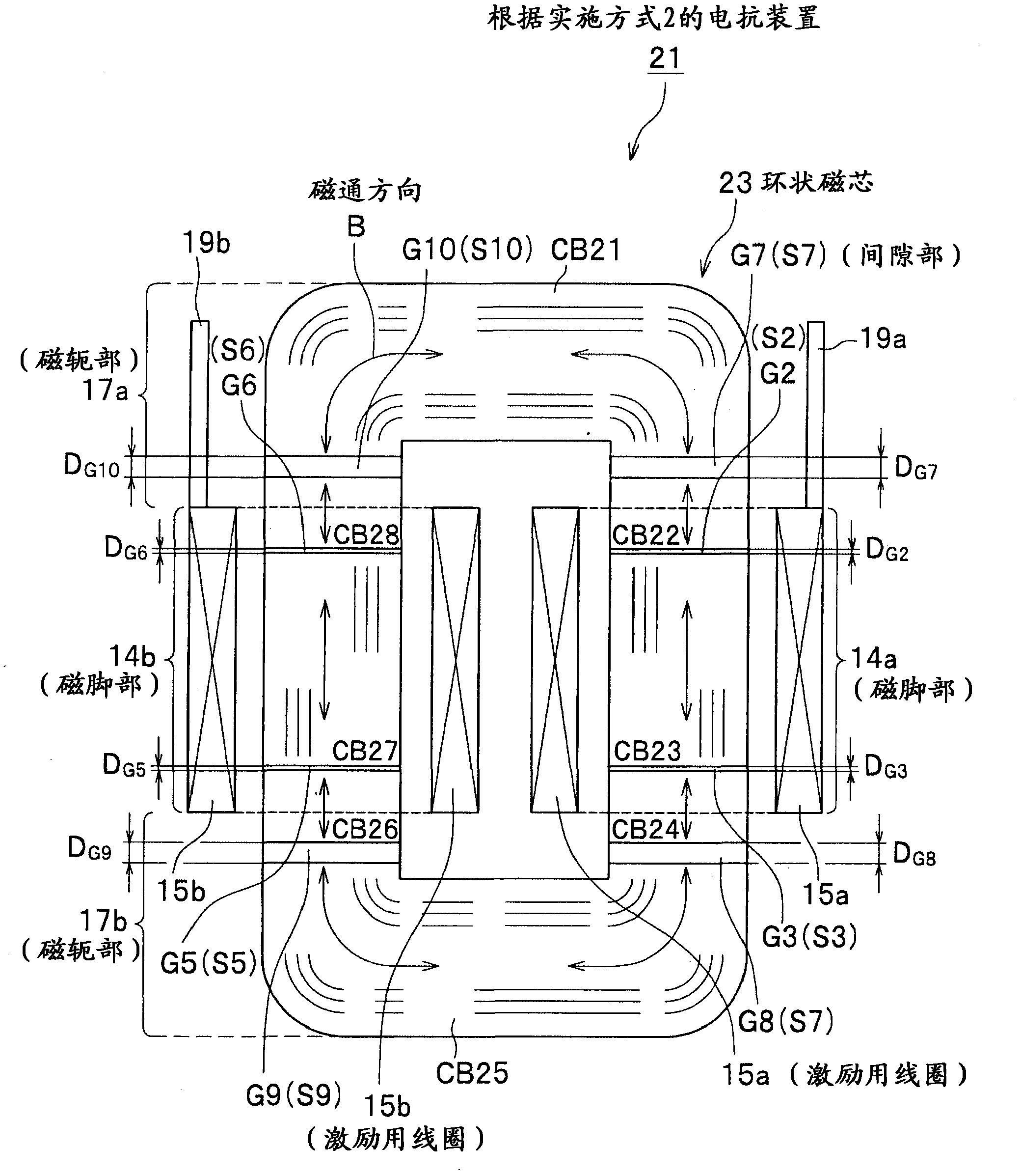
[0054] Next, a reactance device 21 according to Embodiment 2 of the present invention will be described with reference to the drawings. figure 2 It is a front cross-sectional view of the reactance device 21 according to Embodiment 2 of the present invention. The reactance device 11 according to the first embodiment has the same basic constituent elements as the reactance device 21 according to the second embodiment. Therefore, the same reference numerals are assigned to members having the same functions, their repeated descriptions are omitted, and the differences between them will be described.

[0055] Differences between Embodiment 1 and Embodiment 2 are as follows.

[0056] That is, when the toroidal core 13 is viewed on a virtual clock, in the reactance device 11 according to Embodiment 1, it looks like Figure 1A and Figure 1B As shown, a first gap G1 existing in the first yoke portion 17a is provided at the 12 o’clock position, and a fourth gap portion existing in t...

Embodiment approach 3

[0065] Next, a reactance device 31 according to Embodiment 3 of the present invention will be described with reference to the drawings. image 3 is a front cross-sectional view of a reactor 31 according to Embodiment 3 of the present invention. The reactance device 11 according to the first embodiment has the same basic constituent elements as the reactance device 31 according to the third embodiment. Therefore, the same reference numerals are assigned to members having the same functions, their repeated descriptions are omitted, and the differences between them will be described.

[0066] Differences between Embodiment 1 and Embodiment 3 are as follows.

[0067] That is, in the reactor device 11 according to Embodiment 1, the first and second yoke parts 17a, 17b sandwich the first and second magnetic leg parts 14a, 14b and face each other. Figure 1B The paper surface is divided into two in the upper and lower directions. In addition, when the toroidal core 13 is placed on...


PUM


Abstract

The invention provides a reactor and a power converter using the same. By using the reactor and the power converter, the loss of the reactor caused by the leakage of the magnetic flow from a gap can be prevented as much as possible, even when the gap exists in the ringed core area of the magnetic excitation coil. The reactor (11) includes a ringed core (13) and a magnetic excitation coil (15a, 15b). The ringed core (13) includes a plurality of core blocks (CB) made of a magnetic material which are connected in a ring through gaps (G). The magnetic excitation coil (15) is wound around the ringed core (13). The ringed core (13) has a magnetic leg region (14a, 14b) around which the magnetic excitation coil (15a, 15b) is wound and a yoke portion region (17a, 17b) where the magnetic excitation coil (15a, 15b) is not wound. A length of the gap in the magnetic leg region (14a, 14b) is smaller than a length of the gap in the yoke portion region (17a, 17b).

Description

technical field [0001] The present invention relates to a reactor including an annular core made of a magnetic material, an excitation coil wound around the annular core, and a power conversion device using the reactor. Background technique [0002] A reactance device generally includes a ring-shaped core made of a magnetic material, and an excitation coil wound around the ring-shaped core. In the reactance device, magnetic flux is generated in the toroidal core by energizing the excitation coil. Gaps are provided at various positions of the annular core so that the magnetic flux thus generated falls within the range of the saturation magnetic flux density of the magnetic material of the annular core (for example, refer to Patent Documents 1 and 2). [0003] <Patent Document 1> Japanese Unexamined Patent Publication No. 2009-259971 [0004] <Patent Document 2> Japanese Unexamined Patent Publication No. 2008-263062 Contents of the invention [0005] (problem ...

Claims


Application Information

Patent Timeline
Patent Type & Authority Applications(China)
IPC IPC(8): H01F17/06H01F27/24H02M1/12
CPCH01F2038/026H01F3/14H01F27/2895H01F17/06H01F27/346
Inventor 栗田直幸恩田谦一
Owner HITACHI LTD
Why Eureka
Try Eureka