Blower

一种鼓风装置、风扇的技术,应用在用于弹性流体的泵送装置的部件、非变容式泵、机器/发动机等方向,能够解决通过的距离短、鼓风效率降低等问题

Active Publication Date: 2012-09-19
PANASONIC CORP
View PDF5 Cites 3 Cited by
  • Summary
  • Abstract
  • Description
  • Claims
  • Application Information

AI Technical Summary

Problems solved by technology

[0006] In this existing blower device, the distance that the air passes in the adapter 112 is short
In addition, since the cross-sectional shape changes rapidly from the square of the adapter inlet 109 to the circular shape of the duct connection port 111, there is a problem that there is a pressure loss in the flow of air from the fan 106, and the blowing efficiency is reduced. noise due to turbulent flow

Method used


Image

  • Blower
  • Blower
  • Blower

Examples


Embodiment approach

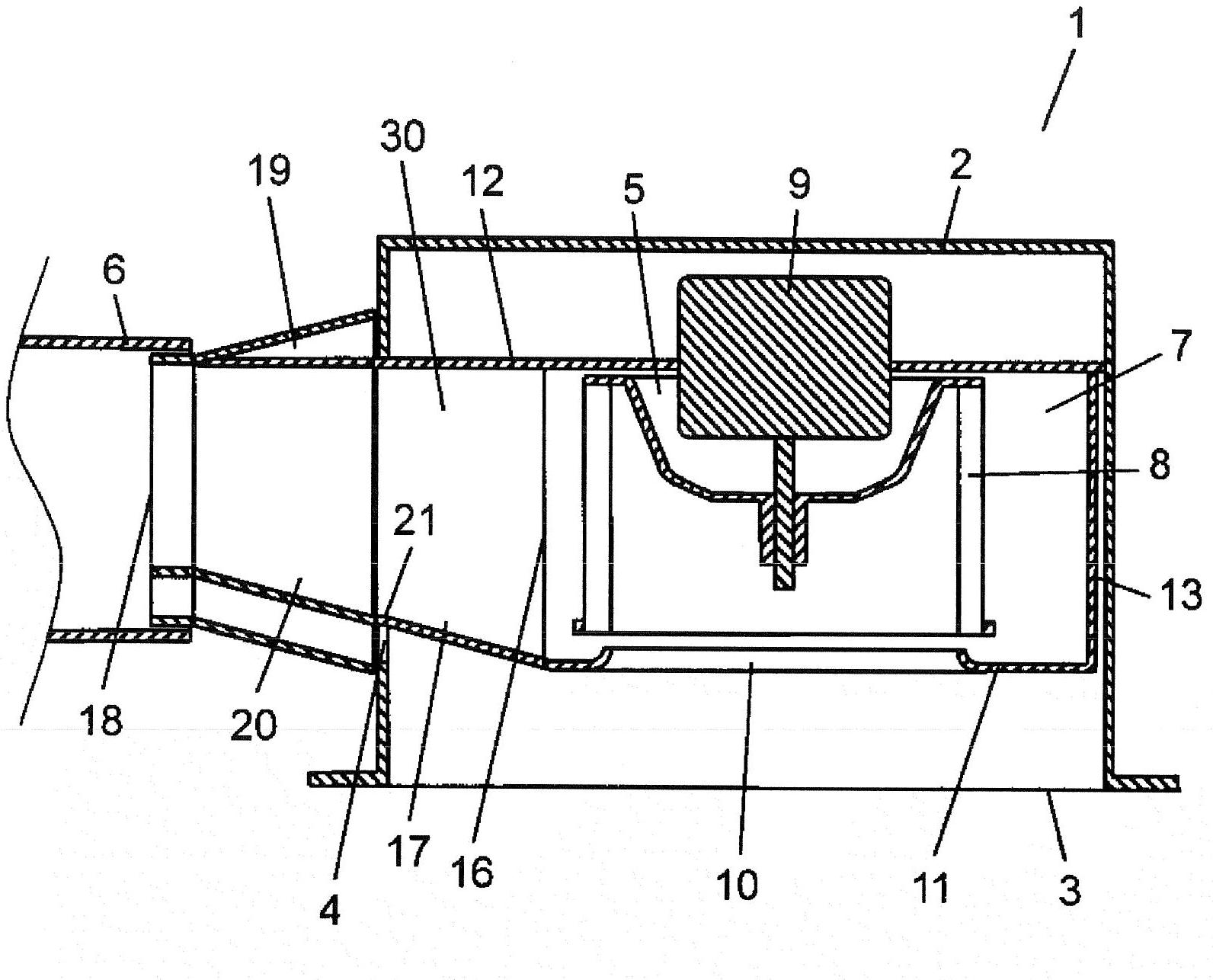
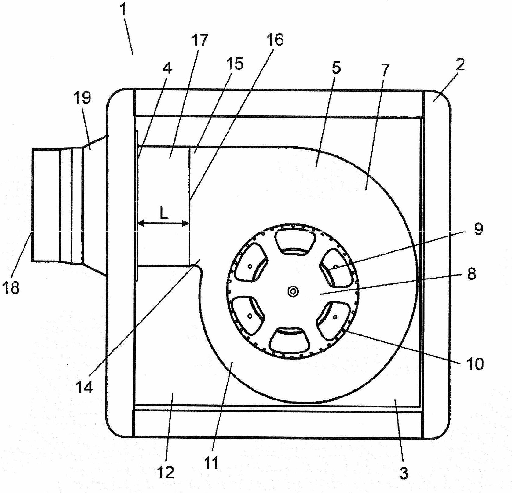
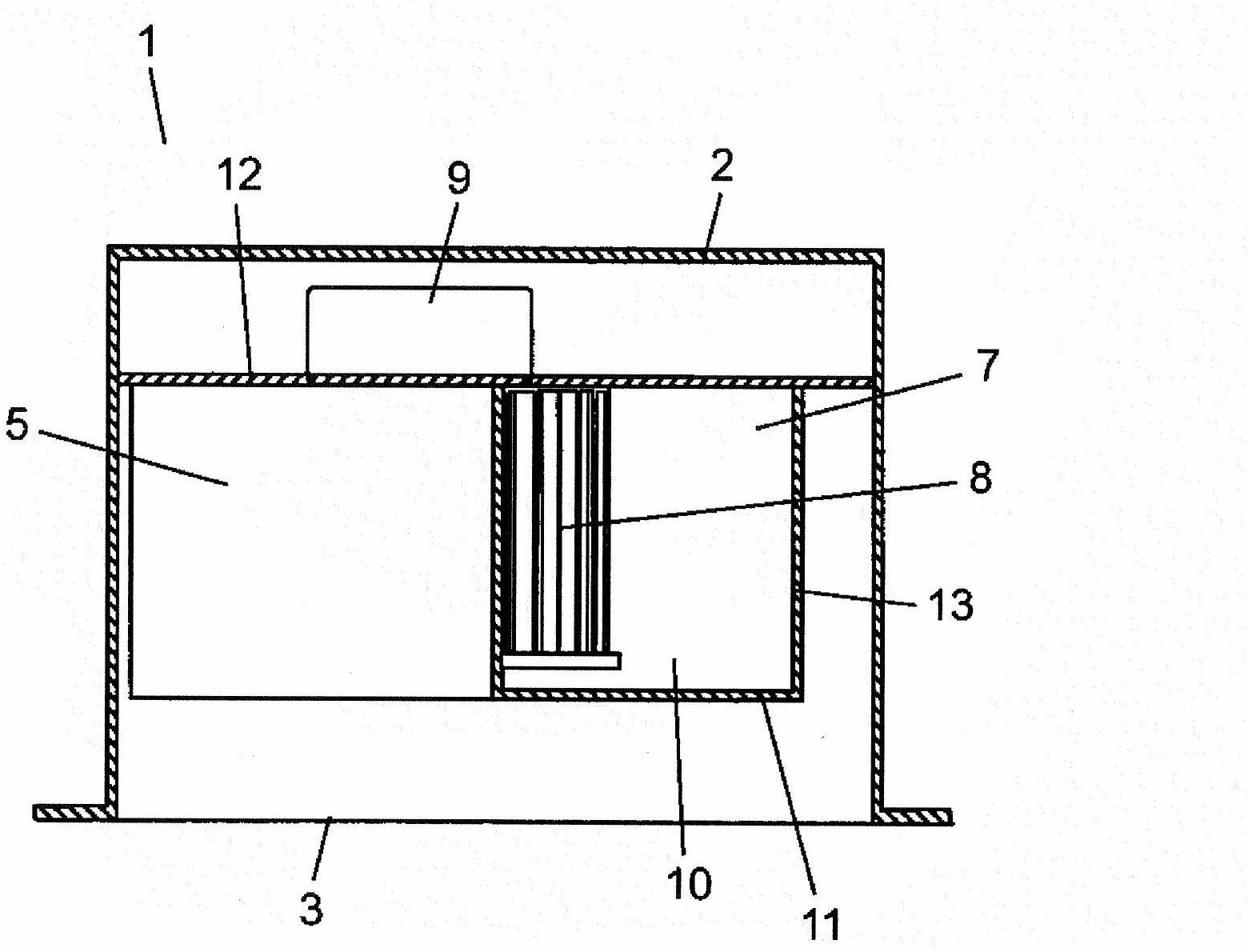
[0023] figure 1 Is a side cross-sectional view showing a blower device according to an embodiment of the present invention, figure 2 It is a plan view seen from the suction port of the casing of the blower. The blower device 1 has a rectangular parallelepiped (for example, length 270mm×width 270mm×height 200mm) frame 2 with a frame suction port 3 on the lower surface of the frame 2, and a frame blowing port on the side 4.

[0024] In addition, a fan 5 is arranged inside the housing 2. The fan 5 is driven by a motor 9 and has a fan outlet 16. The type of the fan 5 is a centrifugal fan that can reliably exhaust air even when the static pressure load on the fan 5 is large when the exhaust duct 6 is long or the like. The fan 5 includes a casing 7 having a scroll-like planar shape, an impeller 8 arranged in the casing 7, and a motor 9 that drives the impeller 8 (for example, a multi-blade impeller having an outer diameter of 145 mm and a height of 100 mm). Since it is a centrifug...


PUM


Abstract

A blower drawing air into the air path and discharging air to the discharge duct, including: a frame forming an outer shell; a fan driven by a motor and having a fan outlet, inside the frame; a duct connection part having a duct connection opening, connected to the discharge duct, outside the frame; and an in-frame blow-out part connecting the duct connection part with the fan outlet, inside the frame. The cross-section shape of the air path changes continuously and smoothly at the in-frame blow-out part and the duct connection part, from the fan outlet to the duct connection opening.

Description

Technical field [0001] The present invention relates to a blower device used for ventilation and air conditioning equipment and the like. Background technique [0002] Conventionally, such a blower is known to be used for a ceiling-buried ventilating fan (for example, refer to Patent Document 1). [0003] Hereinafter, refer to the side cross-sectional view showing the conventional blower Picture 9 The blowing device will be described. [0004] Such as Picture 9 As shown, the air blowing device 101 includes a frame 102, a housing 105, a fan 106, a motor 107, a top plate 108, and an adapter 112. Here, the casing 105 has a scroll shape, and the casing 102 has a casing suction port 103 through which outside air is sucked in and a casing blowout port 104 through which air is blown out. The fan 106 blows air from the casing suction port 103 to the casing blowing port 104. The motor 107 drives the fan 106 to rotate. The top plate 108 fixes the housing 105 and the motor 107. The adaptor...

Claims


Application Information

Patent Timeline
Patent Type & Authority Applications(China)
IPC IPC(8): F04D29/44F04D29/66
CPCF04D29/4226F04D29/626
Inventor 田中有理白滨诚司谷口和宏
Owner PANASONIC CORP
Why Eureka
Try Eureka