
Mechanical time-delay trigger

A delay-triggered, mechanical technology, applied in mechanical equipment, engine components, valve details, etc., to solve problems such as lack of suitable structure and inconvenience for general products

Inactive Publication Date: 2012-09-26
LUOYANG YUFO FIRE FIGHTING EQUIP
View PDF0 Cites 7 Cited by
  • Summary
  • Abstract
  • Description
  • Claims
  • Application Information

AI Technical Summary

Problems solved by technology

[0003] It can be seen that the above-mentioned existing CO2 gas suffocation delay trigger for fire extinguishing in a closed space obviously still has inconvenience and defects in structure and use, and needs to be further improved urgently.
In order to solve the above-mentioned problems, the relevant manufacturers have tried their best to find a solution, but for a long time no suitable design has been developed, and the general product has no suitable structure to solve the above-mentioned problems. This is obviously the relevant industry. Urgent problem

Method used


Image

  • Mechanical time-delay trigger
  • Mechanical time-delay trigger
  • Mechanical time-delay trigger

Examples


Embodiment Construction

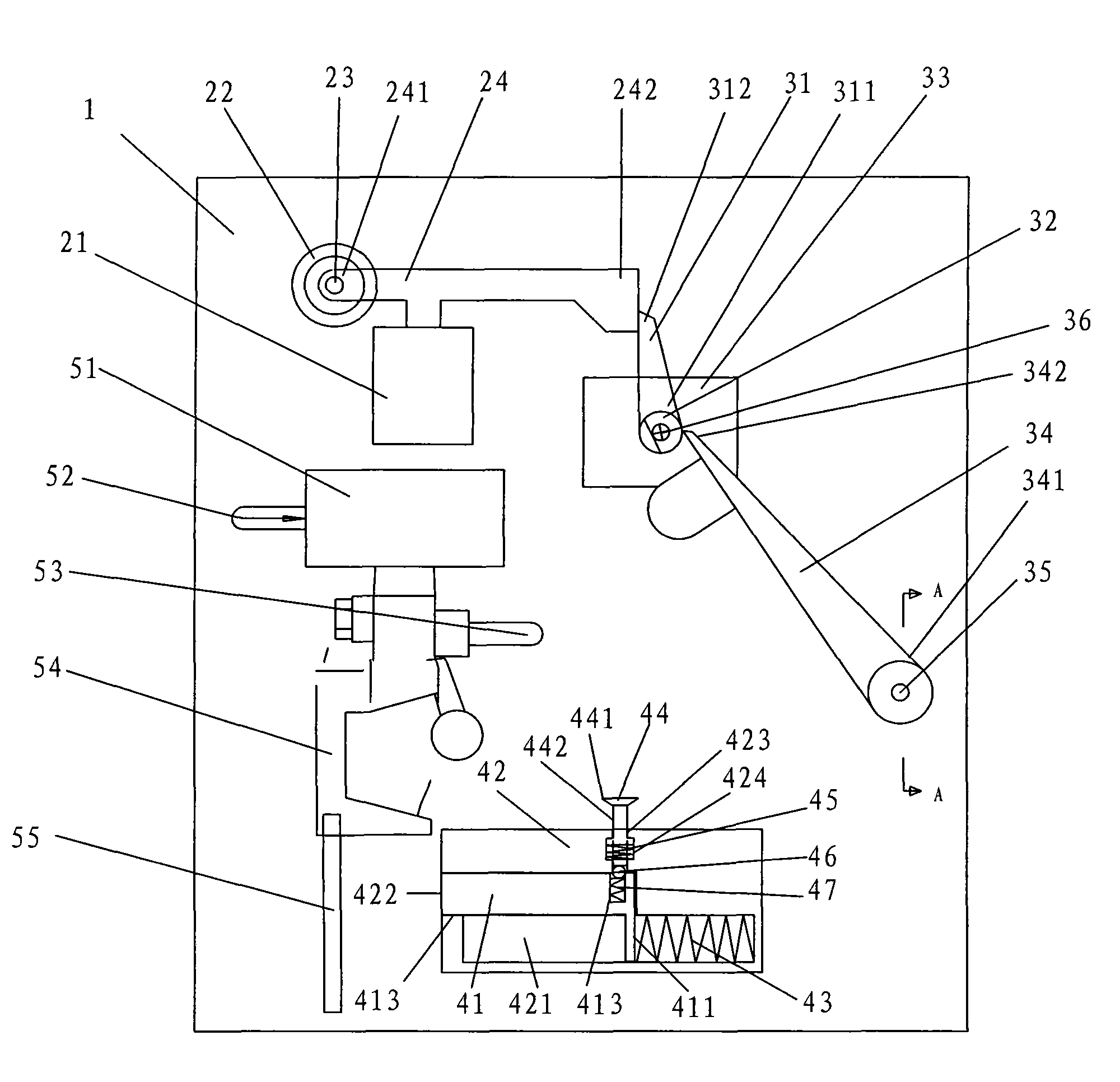
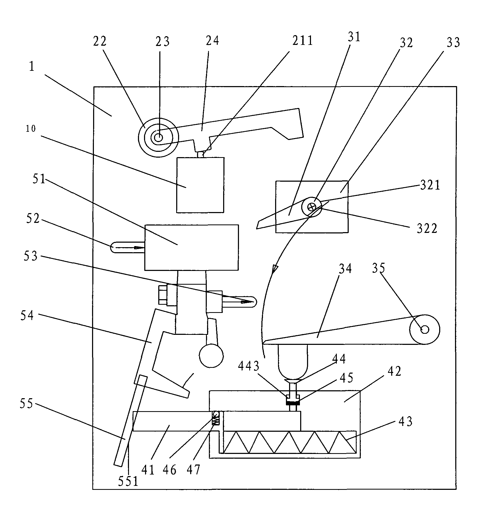
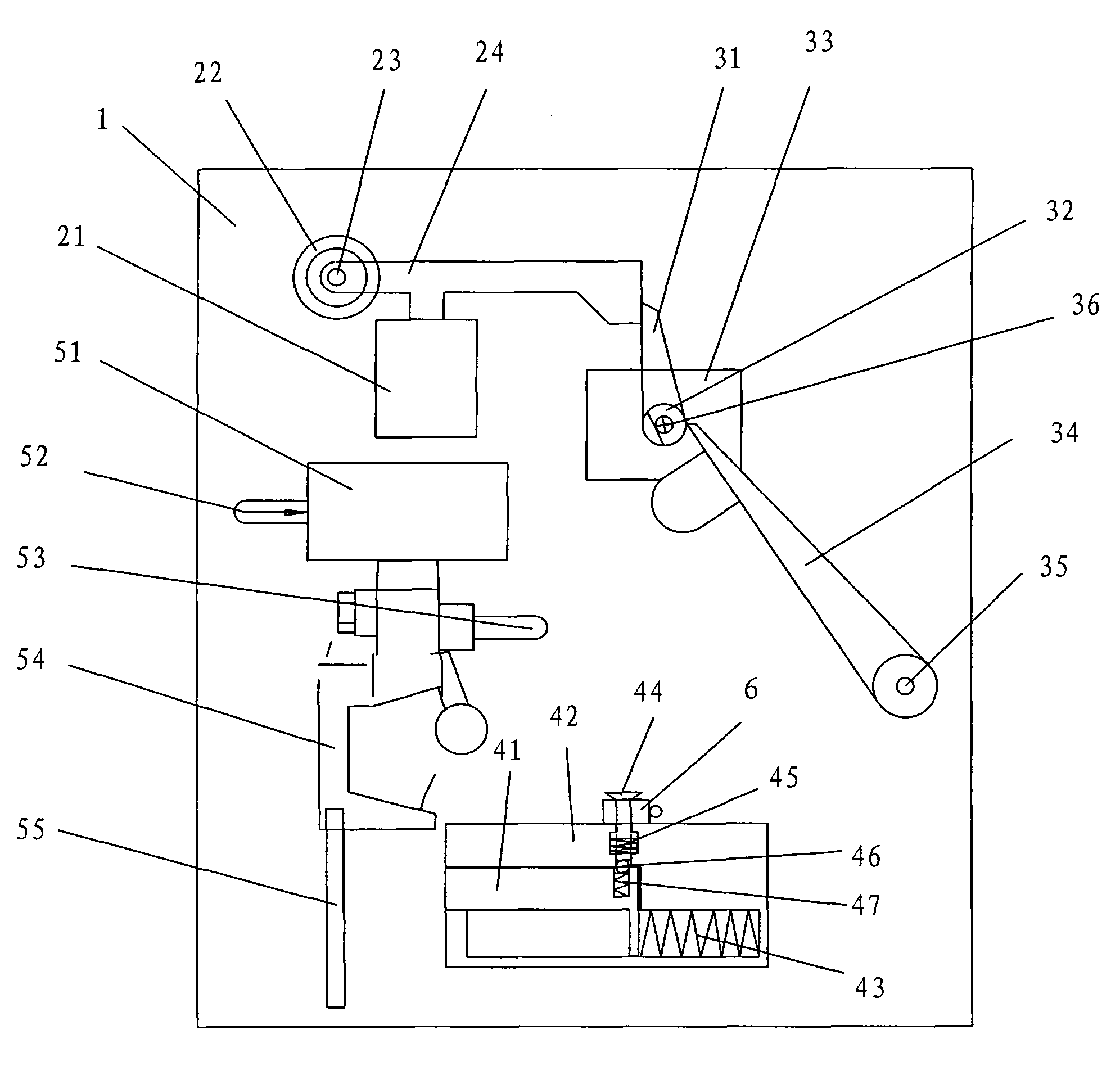
[0038] In order to further illustrate the technical means and effects that the present invention takes to achieve the intended invention purpose, below in conjunction with the accompanying drawings and preferred embodiments, the specific implementation, structure, characteristics and features of the mechanical time-delay trigger proposed according to the present invention will be described below. Efficacy, detailed as follows.

[0039] The aforementioned and other technical contents, features and effects of the present invention will be clearly presented in the following detailed description of preferred embodiments with reference to the drawings. Through the description of the specific implementation mode, a more in-depth and specific understanding of the technical means and effects adopted by the present invention to achieve the intended purpose can be obtained. However, the accompanying drawings are only for reference and description, and are not used to explain the present ...


PUM


Abstract

The invention relates to a mechanical time-delay trigger which ensures reliable time delay by ingeniously using the reliability of a mechanical structure; when the trigger of the invention is at fault, the delay time is prolonged limitlessly without the probability of CO2 jetting in advance; therefore life safety of people possibly existing in a enclosed space is guaranteed, and reliable time for safe evacuation is provided. In addition, the invention is exquisite in structure, and all required parts are integrated on a whole substrate with an area of 300 mm*400 mm. The mechanical time-delay trigger of the invention is also an energy-storage trigger device with compact design; only small force is needed to trigger so as to release great force and realize a long stroke; thus a high pressure CO2 gas valve can be opened reliably, and CO2 gas is released at delayed time; the invention has low cost and high profits.

Description

technical field [0001] The invention relates to a time-delay trigger, in particular to a time-delay mechanical time-delay trigger suitable for CO2 gas suffocation and fire extinguishing in a confined space. Background technique [0002] The CO2 gas suffocation fire extinguishing in the confined space of domestic existing technology, in order to guarantee the life safety of the personnel that may exist in the confined space, make them have time to safely evacuate, what adopt is that electrical equipment (or program) is delayed 10-30 seconds, spray put CO2. It is well known that the delay of electrical appliances (or programs) is not very reliable. It may be affected by various electromagnetic interferences and cause malfunctions. Although various anti-interference measures can be taken to avoid the occurrence of malfunctions, there is still the possibility of malfunctions. . Although the probability of misoperation is very small, once it occurs, it will cause harm to people...

Claims


Application Information

Patent Timeline
Patent Type & Authority Applications(China)
IPC IPC(8): A62C37/00F16K31/06F16K31/12
Inventor 朱桥宇
Owner LUOYANG YUFO FIRE FIGHTING EQUIP
Learn More