Quenching furnace

A technology of quenching furnace and quenching tank, which is applied in the field of quenching furnace, can solve the problems of easy blockage of oil outlet nozzles and complicated disassembly of nozzles, and achieve the effect of improving quenching quality and avoiding carbon formation

Inactive Publication Date: 2013-06-05
苏州工业园区热处理设备厂有限公司
View PDF1 Cites 0 Cited by
  • Summary
  • Abstract
  • Description
  • Claims
  • Application Information

AI Technical Summary

Problems solved by technology

[0007] In order to overcome the problems of easy clogging of oil outlet nozzles and complex disassembly of nozzles in the prior art, the purpose of the present invention is to provide a quenching furnace with an oil curtain mechanism that is easy to maintain and install

Method used


Image

  • Quenching furnace
  • Quenching furnace
  • Quenching furnace

Examples


Embodiment Construction

[0024] The present invention will be further described below in conjunction with accompanying drawing and specific embodiment:

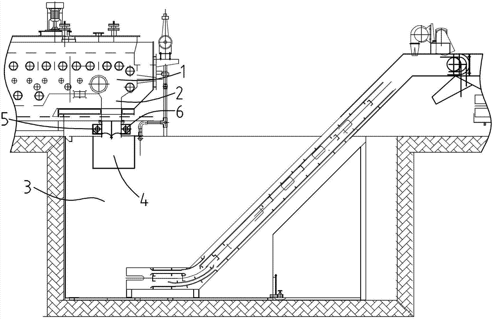
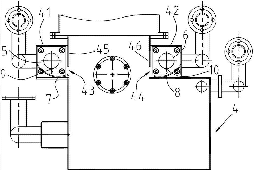
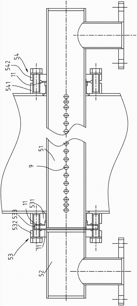
[0025] See attached figure 1 , a quenching furnace of the present invention, comprising a furnace 1, a blanking channel 2 arranged at the discharge end of the furnace 1 and communicated with the quenching tank 3, the lower part of the blanking channel 2 and the quenching tank 3 There is an oil curtain mechanism between them; see attached figure 2 The oil curtain mechanism includes an oil curtain chamber 4 whose upper end communicates with the blanking channel 2 and whose lower end communicates with the quenching tank 3, and the two opposite side walls of the oil curtain chamber 4 are respectively The first oil injection pipe 5 and the second oil injection pipe 6 with the same structure and extending in the transverse direction and the first arc-shaped oil curtain plate 7 located below the first oil injection pipe 5 and the second oil injection pipe...


PUM

PropertyMeasurementUnit
radiusaaaaaaaaaa

Abstract

The invention discloses a quenching furnace, which comprises a hearth, and a blanking channel which is arranged at a discharge end of the hearth and is communicated with a quenching groove; wherein an oil curtain mechanism is arranged between the lower part of the blanking channel and the quenching groove and comprises an oil curtain chamber, the upper end of the oil curtain chamber is communicated with the blanking channel and the lower end of the oil curtain chamber is communicated with the quenching groove; an oil injection pipe which transversely extends and an arc-shaped oil curtain plate which is positioned below the oil injection pipe are respectively arranged on two opposite side walls of the oil curtain chamber; a plurality of nozzles facing towards the arc-shaped oil curtain plate are formed on the oil injection pipe and are axially distributed along the oil injection pipe; and the arc-shaped oil curtain plate is arched downwards and extends towards the blanking channel. Theinvention provides the improved oil curtain mechanism on the basis of related patents, a large amount of steam and a large amount of oil smoke in the quenching groove are effectively prevented from entering the hearth, the problem that an oil duct is frequently blocked is solved, and the maintenance cost of equipment is saved.

Description

technical field [0001] The invention belongs to the field of heat treatment equipment, in particular to a quenching furnace. Background technique [0002] When the workpiece is quenched, it needs to be heated at 850°C in the quenching furnace cavity. When the workpiece in the furnace runs to the end of the conveyor belt, it falls into the blanking channel, immerses in the quenching tank to cool, and finally lifts the workpiece through the quenching tank lifting frame to complete the quenching process. During the quenching process, a large amount of water vapor and oil fume will rise into the furnace, and the workpiece will easily splash into the furnace when the workpiece falls into the quenching tank, resulting in a decrease in the quenching quality of the workpiece. [0003] At present, the latest Chinese patent 200820199488.5 discloses a splash-proof quenching furnace, which has been improved accordingly. This quenching furnace mainly includes a furnace and a quenching ta...

Claims


Application Information

Patent Timeline
Patent Type & Authority Patents(China)
IPC IPC(8): C21D1/62C21D1/63
Inventor 徐益明卢为忠
Owner 苏州工业园区热处理设备厂有限公司
Why Eureka
Try Eureka