
Method and system for separating three-dimensional three-component vector wave field

A vector wave field and three-component technology, which is applied in the field of three-dimensional three-component vector wave field separation, can solve problems such as poor amplitude preservation, neglect of three-component features, and incomplete reception of shear waves, so as to improve accuracy, reduce calculation time, and improve The effect of the signal-to-noise ratio

Active Publication Date: 2013-11-13
北京多分量地震技术研究院
View PDF3 Cites 0 Cited by
  • Summary
  • Abstract
  • Description
  • Claims
  • Application Information

AI Technical Summary

Problems solved by technology

[0007] 2. The shear wave S is not completely received by the R component
For ground three-component seismic exploration data, this patent proposes a method and technical route for affine coordinate transformation and wave field separation. Efficiently restore the full-amplitude properties of wavefields
[0013] The patent (publication number CN101251603A) can only process two components, ignoring the three-component characteristics of the actual collected data; in the process of continuous velocity analysis and extraction, the speed ratio model will destroy the effect of the method; this method damages the three The vector feature of the component seismic signal has poor amplitude preservation, which is not conducive to subsequent interpretation and inversion
In addition, in areas with severe wave pattern leakage, or areas with complex surface signal-to-noise ratios, especially areas with low shallow layers and thin velocity-slow zones, this technology cannot achieve complete wave field separation.
[0014] The above methods can achieve wave field separation to a certain extent, and obtain seismic wave data after suppressing noise, but because they cannot achieve complete wave field separation, the accuracy of seismic data analysis is insufficient.

Method used


Image

  • Method and system for separating three-dimensional three-component vector wave field
  • Method and system for separating three-dimensional three-component vector wave field
  • Method and system for separating three-dimensional three-component vector wave field

Examples


Embodiment Construction

[0073] The implementation of the present invention will be described in detail below in conjunction with the drawings and examples, so that the realization process of how to use technical means to solve technical problems and achieve technical effects in the present invention can be fully understood and implemented accordingly.

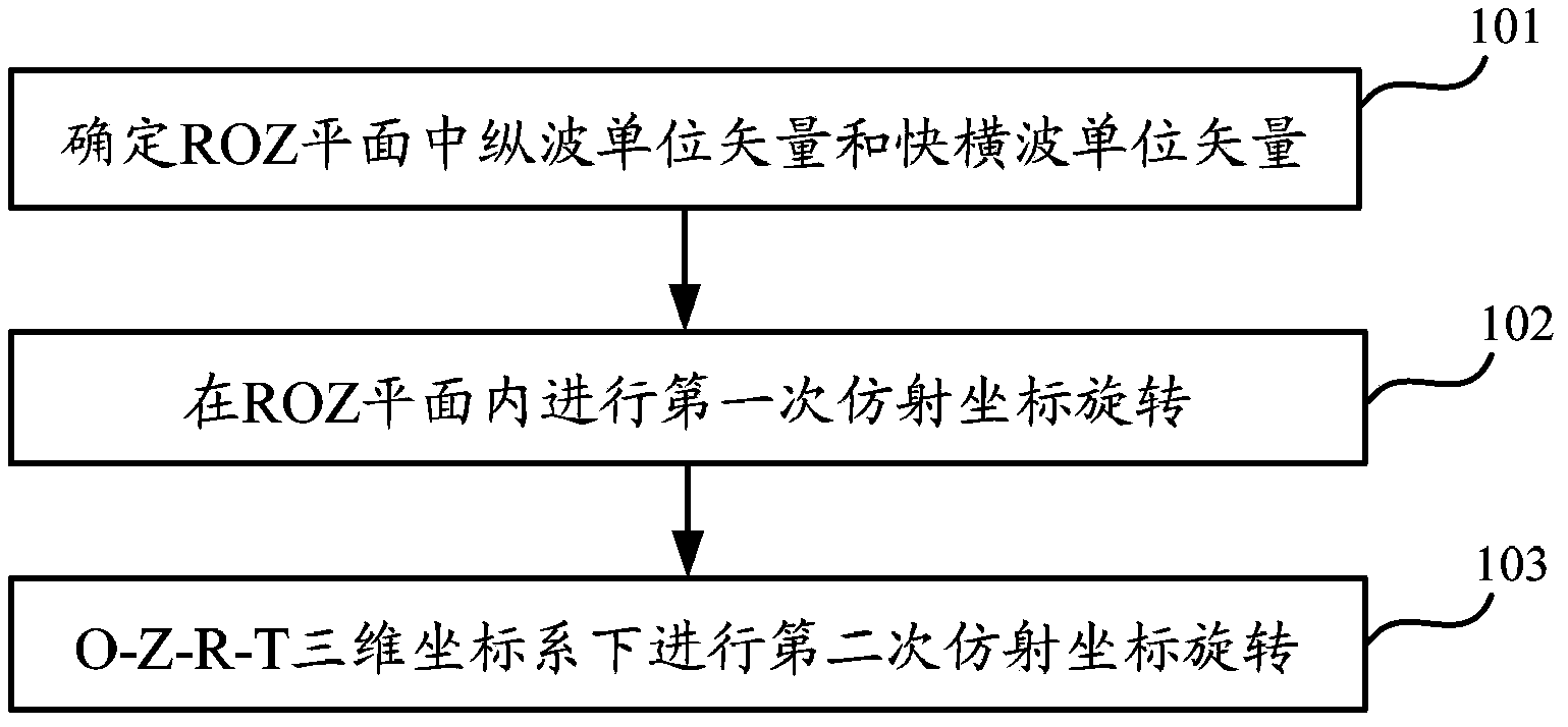
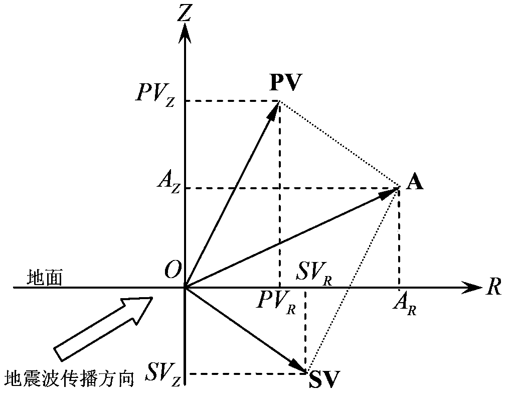
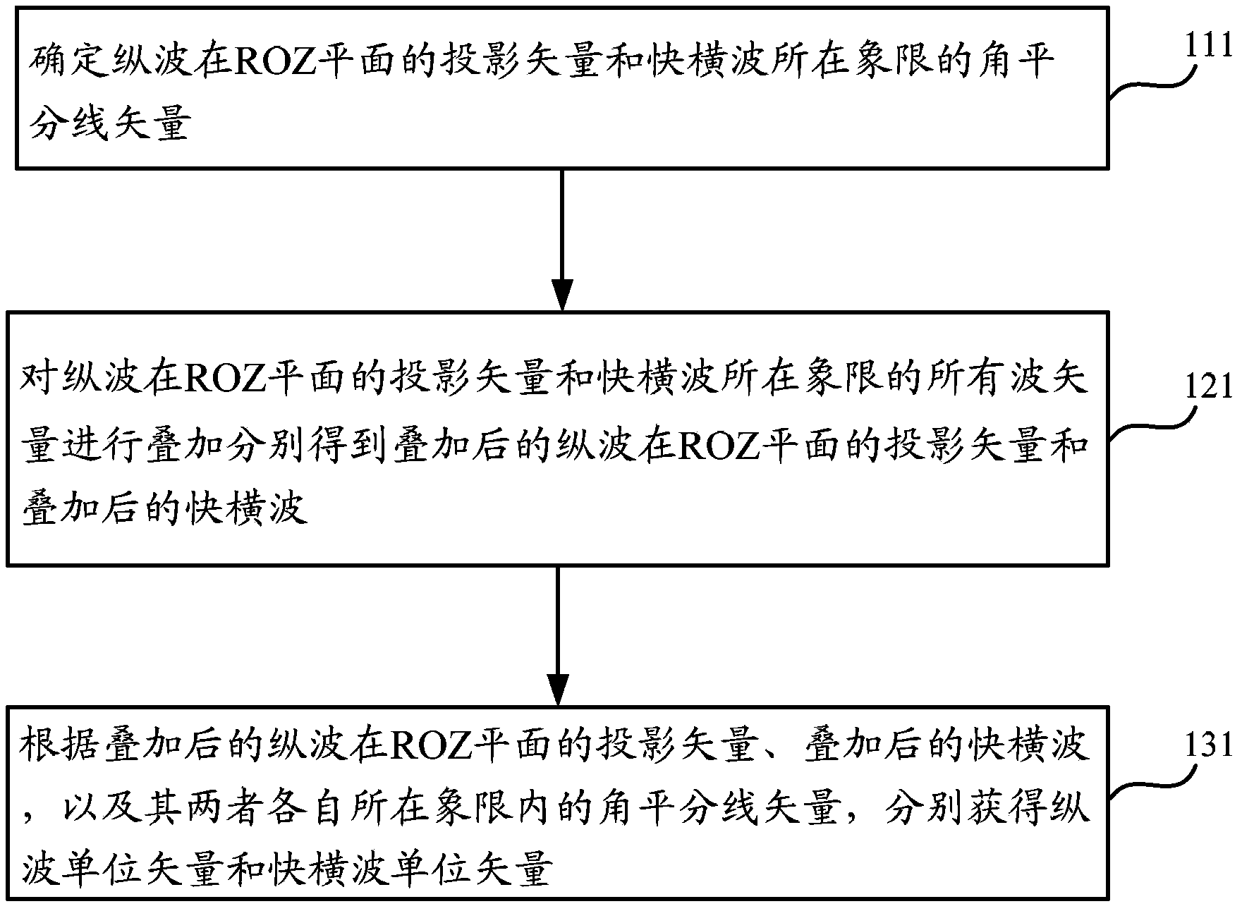
[0074] The core idea of ​​the present invention is: based on the rotation transformation of the two-step affine coordinate system, the "wave pattern leakage" is suppressed, and the vector wave fields of the 3D3C longitudinal wave P, fast shear wave SV, and slow shear wave SH are separated, and the signal of the vector wave field is improved. noise ratio. In the present invention, an orthogonal O-Z-R-T three-dimensional coordinate system is first established, wherein the R-O-Z (ROZ) plane is orthogonal to the R-O-T (ROT) plane, the R-O-Z plane is the incident surface of the longitudinal wave P, the Z-axis direction is vertical to the ground, and the R-a...


PUM


Abstract

The invention discloses a method for separating a three-dimensional three-component vector wave field. The method comprises the following steps of: establishing an orthorhombic O-Z-R-T three-dimensional coordinate system; detecting wave vector directions of a vertical wave, a fast transverse wave and a slow transverse wave; establishing a first affine coordinate system according to the wave vector direction of a projection vector of the vertical wave on an incidence face, and the wave vector direction of the fast transverse wave; rotatably converting vectors Z and R of a receiving coordinate system in the first affine coordinate system, so as to obtain a projection vector of the vertical wave on an R-O-Z plane, and the quick transverse wave; and rotatably converting the projection vector of the vertical wave on the R-O-Z plane and a polarization projection vector on a T axis in a second affine coordinate system, so as to obtain the vertical wave and the slow transverse wave. The method and the device provided by the invention can separate the vector wave fields of the vertical wave P, the fast transverse wave SV and the slow transverse wave SH.

Description

technical field [0001] The invention belongs to the field of seismic data analysis, and in particular relates to a method and system for separating three-dimensional and three-component vector wave fields. Background technique [0002] In three-dimensional three-component vector (3 DIMENSION 3 COMPONENT, 3D3C) seismic exploration, geophones are usually required to receive seismic waves from underground media, including longitudinal waves P and shear waves S. In the O-Z-R-T three-dimensional orthogonal coordinate system defined by it, the longitudinal wave P whose Z component is the vertical component, the R component and the T component receive the shear wave S as the horizontal component, that is, a shear wave rotation transformation in the shear wave S along the X or Y horizontal direction To the R component pointing to the source-receiver azimuth, another shear wave is transformed into the T component orthogonal to the source-receiver azimuth. This process can be called R...

Claims


Application Information

Patent Timeline
Patent Type & Authority Patents(China)
IPC IPC(8): G01V1/28G01V1/36
Inventor 芦俊王赟
Owner 北京多分量地震技术研究院
Learn More