
Rotary table of a photolithography machine

A technology of rotary table and lithography machine, which is used in microlithography exposure equipment, workbench, photolithography process exposure device, etc. The effect of small friction

Active Publication Date: 2015-11-18
SHANGHAI MICRO ELECTRONICS EQUIP (GRP) CO LTD +1
View PDF3 Cites 0 Cited by
  • Summary
  • Abstract
  • Description
  • Claims
  • Application Information

AI Technical Summary

Problems solved by technology

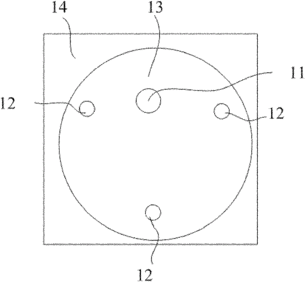
[0007] The technical problem to be solved by the present invention is to provide a rotary table of a lithography machine to solve the problem of large mechanical static difference of the rotary table in the prior art

Method used


Image

  • Rotary table of a photolithography machine
  • Rotary table of a photolithography machine
  • Rotary table of a photolithography machine

Examples


Embodiment Construction

[0026] In order to make the above-mentioned objects, features and advantages of the present invention more obvious and easy to understand, the specific embodiments of the present invention will be described in detail below.

[0027] The rotary table of the lithography machine described in the present invention can be realized in a variety of alternative ways. The following is a description of a preferred embodiment. Of course, the present invention is not limited to this specific embodiment. The well-known general replacements are undoubtedly covered by the protection scope of the present invention.

[0028] Please see Figure 4 , Figure 4 It is a schematic diagram of the top view structure of the rotary table of the lithography machine of the present invention, such as Figure 4 As shown, the lithography machine rotary table of the present invention includes: a substrate 24, a work table 23, a supporting mechanism 22, a rotation center positioning mechanism 21 and a driving mechan...


PUM


Abstract

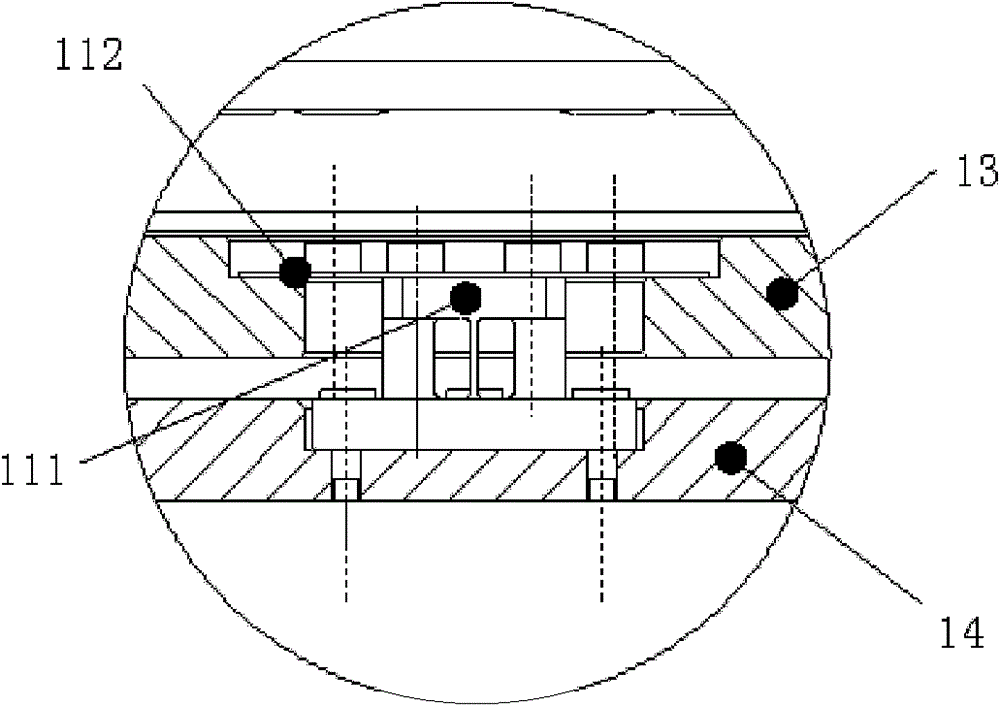
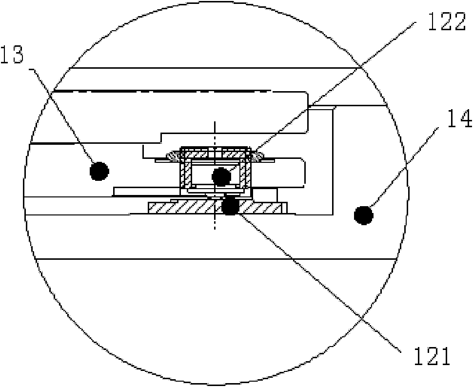
The invention provides a mask aligner rotating platform. A high pressure gas is filled between an air floatation guide way shaft and an air floatation guide way lining of a rotation center positioning mechanism in order to form a gas film with certain stiffness between the air floatation guide way shaft and the air floatation guide way bushing, so that rotational stiffness of the rotation center positioning mechanism is almost zero. Horizontal stiffness can be very high and rotational stiffness is not influenced, so that a mechanical static error of the rotating platform can be effectively reduced. At the same time, each supporting mechanism adopts a first supporting pad and a second supporting pad and the two supporting pads perform surface contact to reduce deformation of contact points, decrease friction, and benefit for reducing the mechanical static error of the rotating platform. The middle of the first supporting platform is provided with a flexure hinge with two directions which can rotate around the center of the flexure hinge to ensure the first supporting pads and the second supporting pads in a plurality of supporting mechanisms maintain surface contact all the time and to improve the stability of the rotating platform.

Description

Technical field [0001] The invention relates to the technical field of semiconductor manufacturing equipment, in particular to a rotary table of a photoetching machine. Background technique [0002] The development of microelectronic technology has promoted the upgrading of computer technology, communication technology and other electronic information technology, and has played an important leading and basic role in the revolution of the information industry. Production equipment plays an important role in the entire microelectronics industry, and in the manufacturing equipment of microelectronic devices, the most important investment and most important is the lithography equipment. With the improvement of integrated circuit integration, the positioning accuracy of the lithography machine is required to be higher and higher, and in the positioning mechanism of the lithography machine, the rotating table plays a very key role. [0003] Patent 200910200944.2 discloses a rotating tab...

Claims


Application Information

Patent Timeline
Patent Type & Authority Patents(China)
IPC IPC(8): G03F7/20B25H1/14
Inventor 范哲光周清华齐芊枫吴立伟王鑫鑫
Owner SHANGHAI MICRO ELECTRONICS EQUIP (GRP) CO LTD
Learn More