Signal time frequency characteristic image generation method and device thereof

An image generation device and technology of time-frequency characteristics, which are applied in the field of signal processing to achieve the effect of eliminating cross terms and high time-frequency resolution

Inactive Publication Date: 2012-09-26
SUZHOU UNIV
View PDF3 Cites 9 Cited by
  • Summary
  • Abstract
  • Description
  • Claims
  • Application Information

AI Technical Summary

Problems solved by technology
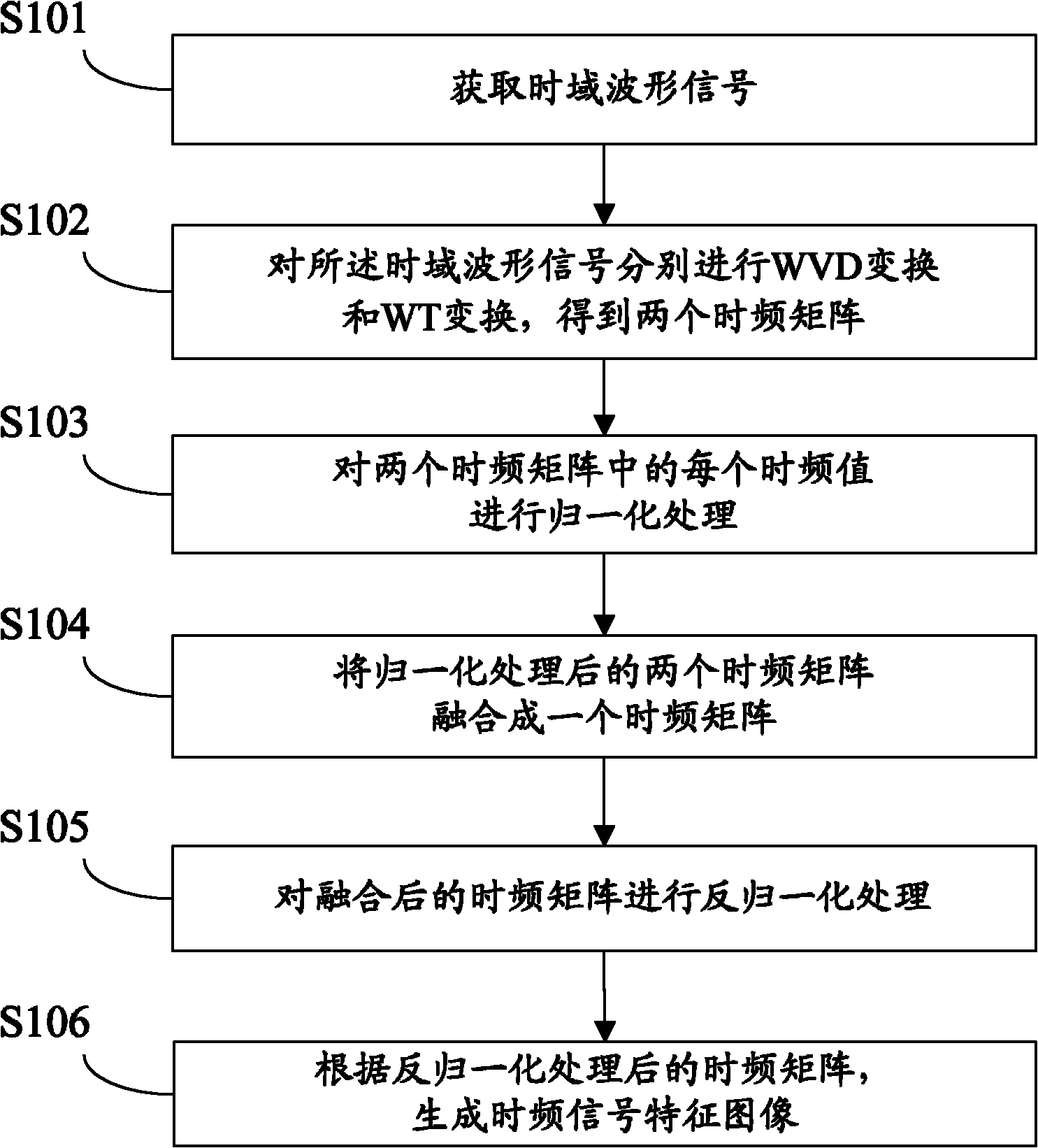
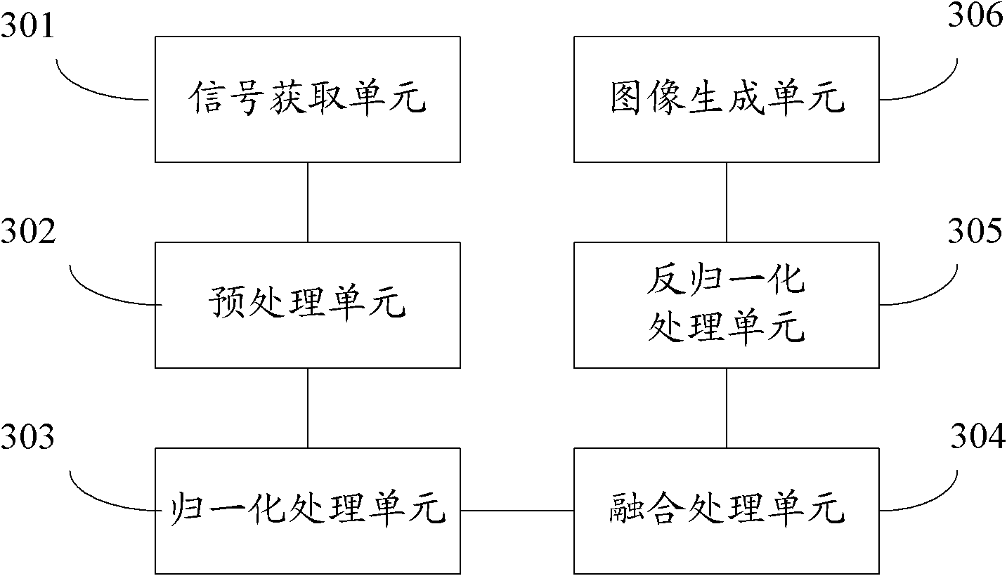
Compared with the windowed time-frequency variation, the bilinear time-frequency distribution has a higher time-frequency resolution, but due to its inherent bilin...

Method used


Image

  • Signal time frequency characteristic image generation method and device thereof
  • Signal time frequency characteristic image generation method and device thereof
  • Signal time frequency characteristic image generation method and device thereof

Examples


example 1

[0099] Example 1: Application in bearing outer ring fault detection

[0100] The outer ring of the bearing is the main part of the bearing fault. When there is a partial fault in the outer ring of the bearing, the vibration of the bearing has an impact response vibration due to the rolling body passing through the outer ring. The impact response signal is a non-stationary signal, so this method can be used The method for generating the signal time-frequency characteristic image of the invention determines the distribution of the energy of the vibration response signal with time and frequency.

[0101] The test object is a tapered roller bearing at the shaft end of a reducer. The bearing model is 33207. A 0.6mm through-crack fault is set on the outer ring of the bearing by wire cutting to simulate serious faults and minor faults on the outer ring of the bearing. The bearing structural parameters are as follows: number of rolling elements Z = 17, rolling element diameter d = 9mm...

example 2

[0107] Example 2: Application in Gear Fault Feature Detection

[0108] When the gearbox is in normal operation, there is a meshing frequency in the vibration signal due to the impact every time the gear meshes; when the gearbox is faulty, there is also an impact frequency caused by the fault in addition to the meshing frequency. In order to describe the variation of energy in the vibration signal with time and frequency, the signal time-frequency characteristic image generation method of the present invention can be used to determine the distribution of energy of the vibration response signal with time and frequency.

[0109] The test object is LC5T81 gearbox, which has 5 forward gears and 1 reverse gear, such as Figure 9 shown. This paper takes the third gear as the research object, and mainly measures the gear vibration acceleration signal of the serious fault of the third gear (broken third gear). The meshing frequency of the third gear of the gearbox is 500Hz, and the sa...


PUM


Abstract

The invention discloses a signal time frequency characteristic image generation method. The method comprises the following steps of: acquiring a time domain waveform signal; carrying out Wigner-Ville distribution transform (WVD) and wavelet transform (WT) on the time domain waveform signal respectively to obtain two time frequency matrices; carrying out normalization processing on each time frequency value in the two time frequency matrices; merging the two time frequency matrices which are subjected to the normalization processing into one time frequency matrix; carrying out inverse normalization processing on the merged time frequency matrix; according to the time frequency matrix which is subjected to the inverse normalization processing, generating a signal time frequency characteristic image. The invention also discloses a signal time frequency characteristic image generation device. A generated signal time frequency characteristic image by using the method or the device has a higher time frequency resolution, and an introduced cross term when generating the image can be eliminated.

Description

technical field [0001] The invention relates to the technical field of signal processing, in particular to a method and device for generating a time-frequency characteristic image of a signal. Background technique [0002] Joint Time-Frequency Analysis (JTFA) is referred to as Time-Frequency Analysis. Time-frequency analysis is a powerful tool for analyzing time-varying non-stationary signals. The time-frequency analysis method provides the joint distribution information of the time domain and the frequency domain, and can describe the relationship of the signal frequency with time. The image generated by time-frequency analysis method is called signal time-frequency characteristic image. [0003] There are two methods for generating time-frequency feature images of signals in the prior art: one is a windowed time-frequency transformation method, and the other is a bilinear (Cohen-like) time-frequency distribution method. [0004] The main principle of the windowed time-f...

Claims


Application Information

Patent Timeline
IPC IPC(8): G06T11/00
Inventor 黄伟国龚海健赵凯朱忠奎
Owner SUZHOU UNIV
Why Eureka
Try Eureka