A cross-subframe interference detection method, positioning method and base station
A cross-subframe and interference detection technology, applied in electrical components, wireless communication, etc., can solve the problems of increased difficulty in network planning and deployment, and the inability to realize cross-subframe interference detection, so as to reduce difficulty, accurately cross-subframe interference, The effect of accurate detection
- Summary
- Abstract
- Description
- Claims
- Application Information
AI Technical Summary
Problems solved by technology
Method used
Image
Examples
Embodiment 1
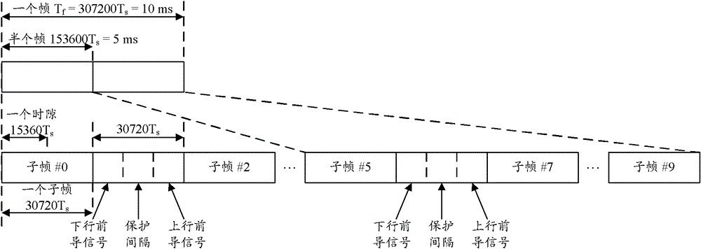
[0042] Before taking the TD-LET system as an example to describe the cross-subframe interference detection method provided by the present invention, in order to facilitate the understanding of the solution, the relevant protocols of the TD-LTE system are briefly introduced, as follows:
[0043] Firstly, the structure of the transmission time slot of DwPTS in the TD-LET system is introduced, such as Figure 4A As shown, it is a typical structure of the transmission time slot of DwPTS, including the downlink control channel PDCCH, the primary synchronization channel P-SCH and the downlink service shared channel PDSCH, such as Figure 4B As shown, it is another typical structure of the transmission time slot of DwPTS, which only includes PDCCH and P-SCH, but does not include PDSCH.
[0044] Among them, the PDCCH contains downlink / uplink resource call information and occupies the entire frequency band bandwidth;
[0045] The P-SCH only uses the central 1.08MHz bandwidth of the en...
Embodiment 2
[0088] After the cross-subframe interference detection method in Embodiment 1 detects that the base station is interfered by the cross-subframe interference of the interference source base station, the processing flow of locating the interference source base station can also be started, such as Figure 8 shown, including:
[0089] Step S801, the base station synchronizes with the base station of the interference source.
[0090] Step S802, receiving a broadcast message sent by the base station of the interference source.
[0091] Step S803. Obtain the global cell identity (CGI) of the interference source base station from the received broadcast message.
[0092] The specific processing flow of the above interference source base station positioning scheme is as follows: Figure 9 shown, including:
[0093] In step S901, after determining that the base station is interfered by the cross subframe of the interference source base station, the base station starts a processing pro...
Embodiment 3
[0103] Based on the same inventive concept, according to the cross-subframe interference detection method and the interference source base station positioning method provided in the above-mentioned embodiments of the present invention, another embodiment of the present invention also provides a base station, the schematic diagram of which is as follows Figure 10 shown, including:
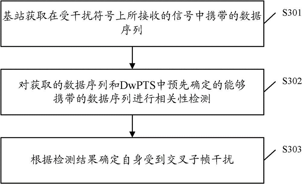
[0104] An obtaining unit 1001, configured to obtain a data sequence carried in a signal received on an interfered symbol;
PUM
 Abstract
Description
Claims
Application Information
 - R&D
- Intellectual Property
- Life Sciences
- Materials
- Tech Scout
- Unparalleled Data Quality
- Higher Quality Content
- 60% Fewer Hallucinations
Browse by: Latest US Patents, China's latest patents, Technical Efficacy Thesaurus, Application Domain, Technology Topic, Popular Technical Reports.
© 2025 PatSnap. All rights reserved.Legal|Privacy policy|Modern Slavery Act Transparency Statement|Sitemap|About US| Contact US: help@patsnap.com


