Multipoint floating locking device for printed circuit board

A printed circuit board and locking device technology, applied to the circuit layout, fixing device, elastic/clamping device and other directions on the support structure, can solve the problems of inconvenient disassembly and assembly of the printed circuit board, and achieve the improvement of heat conduction efficiency and structural design. Simple, reliable results

Inactive Publication Date: 2012-09-26
上海美多通信设备有限公司
View PDF22 Cites 6 Cited by
  • Summary
  • Abstract
  • Description
  • Claims
  • Application Information

AI Technical Summary

Problems solved by technology

[0003] Aiming at the problem in the prior art that the inner cavity of the instrument and meter equipment box is a blind cavity, which makes it very inconvenient to disassemble and assemble the printed c

Method used


Image

  • Multipoint floating locking device for printed circuit board
  • Multipoint floating locking device for printed circuit board
  • Multipoint floating locking device for printed circuit board

Examples


Embodiment 1

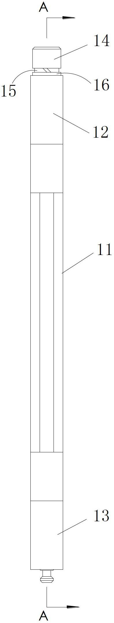
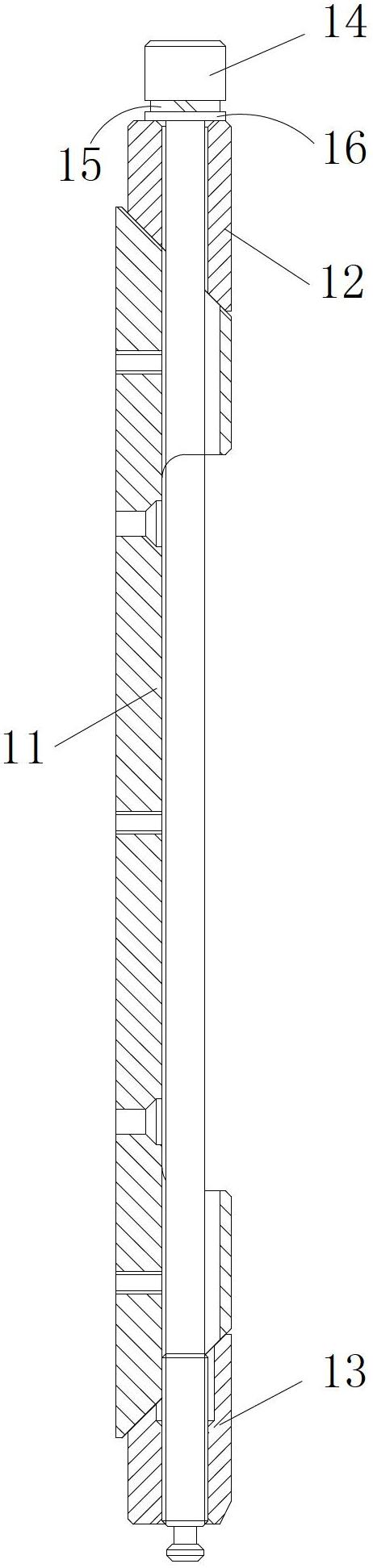
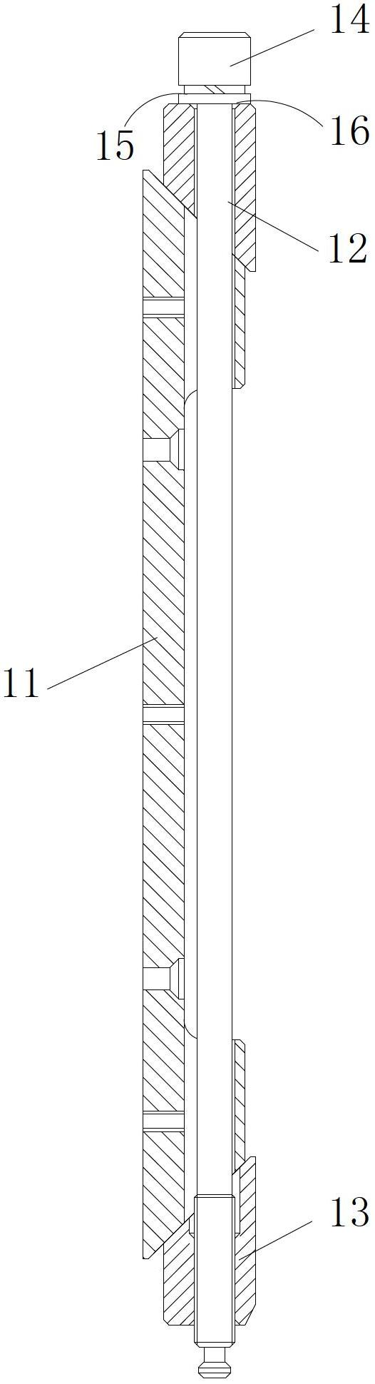
[0029] see figure 1 , figure 2 , image 3 The shown multi-point floating locking device for printed circuit boards includes a base 11, an outer locking slider 12, an inner locking slider 13 and bolts 14, and the longitudinal section of the base 11 is an isosceles trapezoid , the outer locking slider 12 is arranged in front of the base 11, the inner locking slider 13 is arranged at the rear of the base 11, the inner end of the outer locking slider 12 and the inner end of the inner locking slider 13 respectively adopt The slope structure, the slope angles of the slopes at the inner end of the outer locking slider 12 and the slopes at the inner end of the inner locking slider 13 correspond to the slope angles at both ends of the base 11 . The outer locking slider 12, the base 11 and the inner locking slider 13 are connected to form a cuboid, the outer locking slider 12, the base 11 and the inner locking slider 13 respectively offer through holes along the axis of the cuboid, a...

Embodiment 2

[0032] see again Figure 4 , Figure 5 As shown, the difference between this embodiment and Embodiment 1 is that two bases are arranged in sequence along the longitudinal direction of the printed circuit board, and the two bases are connected in series through the middle locking slider 17, and the middle locking The two ends of the tight slider 17 respectively adopt inclined-plane structures, and the inclined angles of the inclined surfaces at both ends of the middle locking slider 17 correspond to the inclined angles of the front and rear base 11 two ends respectively. The longitudinal section of the middle locking slider 17 can be an isosceles triangle or an isosceles trapezoid. When the bolt moves radially along the through hole of the base, it will drive the outer locking slider, the inner locking slider and the middle locking slider to move outward synchronously and be tightly connected with the printed circuit board isolation block, so that the printed circuit board Th...


PUM


Abstract

The invention discloses a multipoint floating locking device for a printed circuit board. The multipoint floating locking device comprises a base, an outer locking sliding block, an inner locking sliding block and a bolt, wherein the outer locking sliding block, the base and the inner locking sliding block are connected to form a cuboid, and the bolt sequentially passes through a through hole of the outer locking sliding block and a through hole of the base and then is in threaded connection with the inner locking sliding block. The bottom surface of the base is fixedly connected with a printed circuit board, and the bolt is driven to rotate by inserting a tool into an internal hex hole at the head of the bolt, so that the bolt moves along the radial direction of the through hole of the base, thereby driving the outer locking sliding block and the inner locking sliding block to synchronously move outwards along the inclined end surface of the base and to be closely connected with a printed circuit board partition block fixedly arranged on a box body; and therefore, a new technical scheme is provided for the installation and fixing of the printed circuit board.

Description

technical field [0001] The invention relates to printed circuit boards in instruments and instrumentation equipment, and more specifically relates to a multi-point floating locking device for printed circuit boards. Background technique [0002] Printed circuit boards are generally used in various instruments and instrumentation equipment. The installation and fixing of printed circuit boards generally adopt the forms of screws, pressure plates, slots, and spring sheets. However, at present, the depth of many instruments and instrument cabinets is much larger than the height, and the entire cabinet cavity will form a blind cavity, which makes it very inconvenient to disassemble and assemble the printed circuit board. Contents of the invention [0003] Aiming at the problem in the prior art that the inner cavity of the instrument and meter equipment box is a blind cavity, which makes it very inconvenient to disassemble and assemble the printed circuit board, the purpose of ...

Claims


Application Information

Patent Timeline
IPC IPC(8): H05K7/12F16B1/04
Inventor 马文平程卫红
Owner 上海美多通信设备有限公司
Why Eureka
Try Eureka