Turbo compressor

A technology of turbo compressor and compressor casing, applied in the field of turbo compressor

Active Publication Date: 2012-09-26
KAESER KOMPRESSOREN SE
View PDF10 Cites 3 Cited by
  • Summary
  • Abstract
  • Description
  • Claims
  • Application Information

AI Technical Summary

Problems solved by technology

[0003] This type of turbo compressor is not designed for the best possible operation at volume flows well below those set for the design point

Method used


Image

  • Turbo compressor
  • Turbo compressor
  • Turbo compressor

Examples


Embodiment Construction

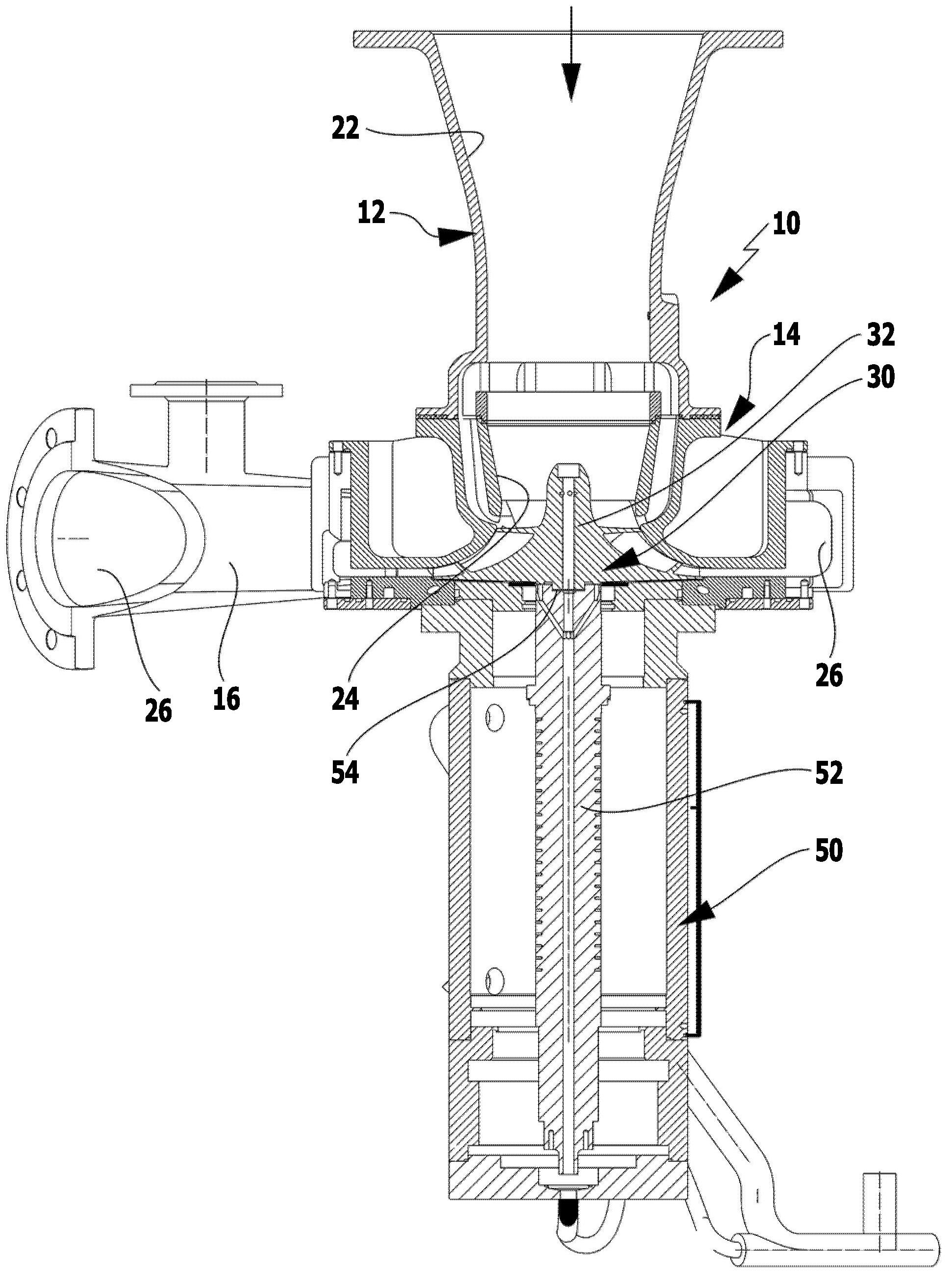
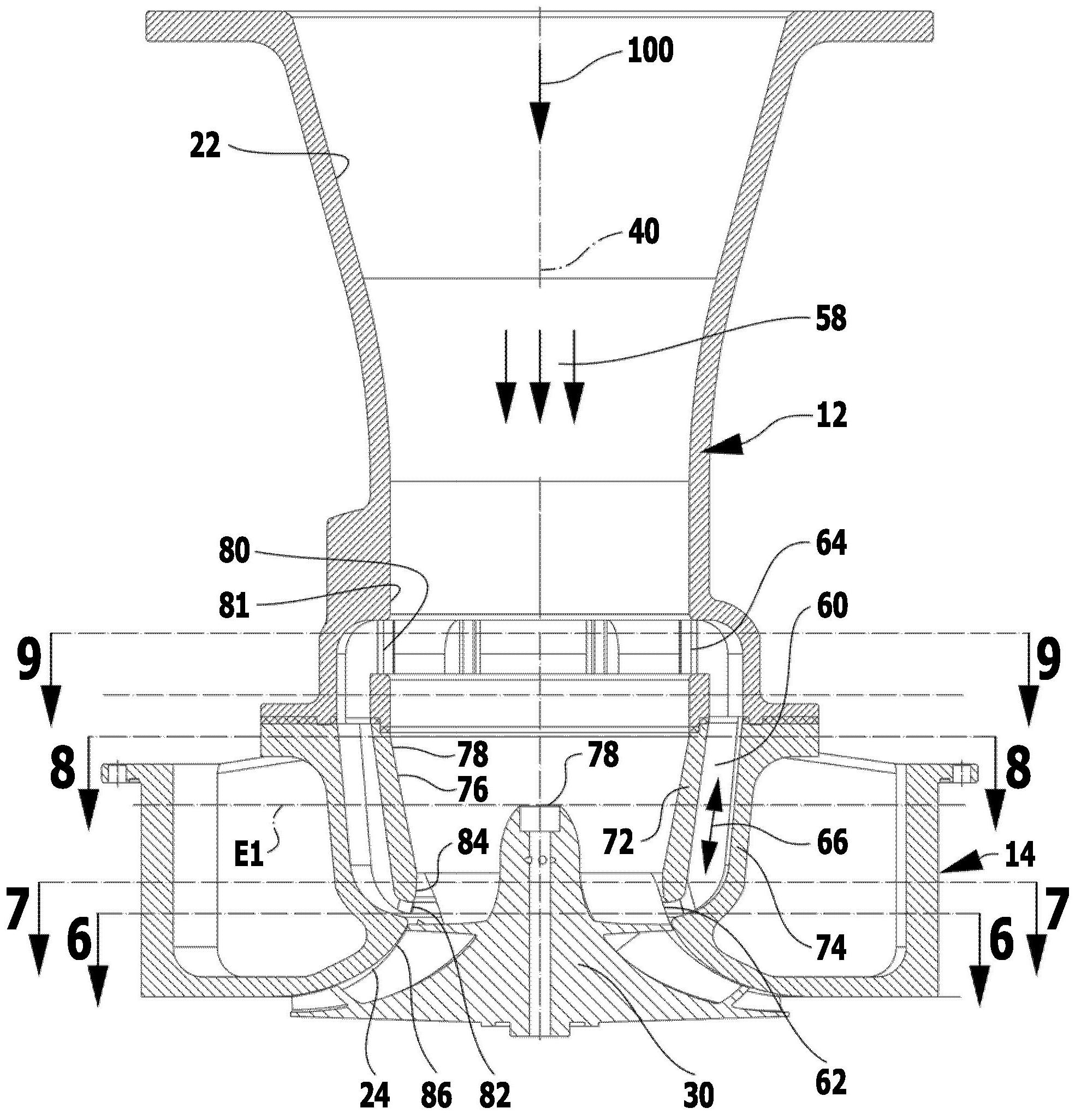
[0071] According to the turbo compressor of the present invention figure 1 The embodiment shown in includes a compressor housing, generally designated 10 , comprising an intake housing 12 , an impeller housing 14 and a discharge housing 16 .

[0072] The intake housing 10 at least partially forms an intake duct 22 which transitions in the impeller housing 14 into an impeller duct 24 and which in turn transitions into an exhaust duct 26 in the exhaust housing 16 .

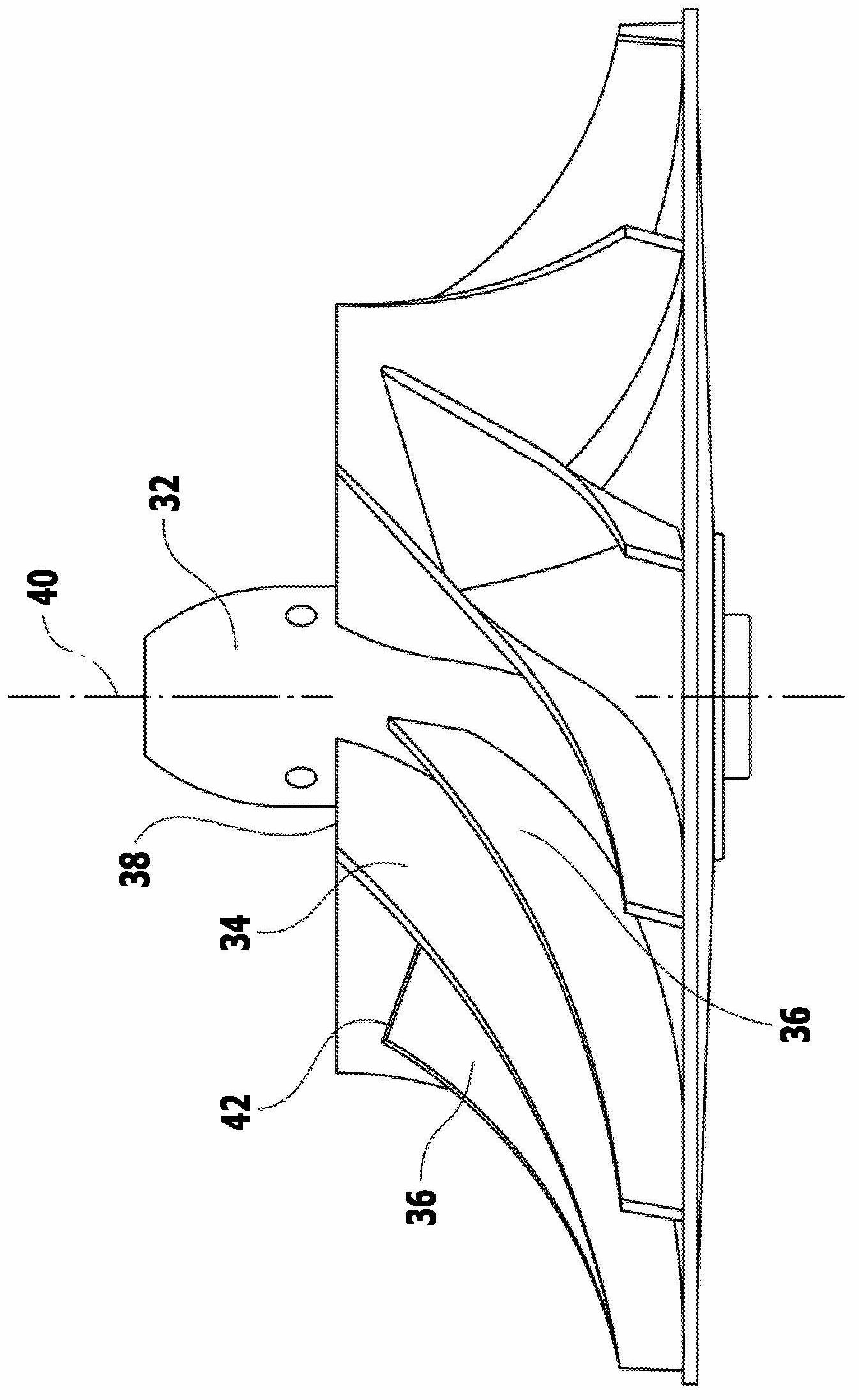
[0073] In the impeller channel 24 is provided an impeller as a whole marked with 30, the impeller as figure 2 shown in includes a hub body 32 on which impeller blades 34 and 36 are arranged, wherein the impeller blade 34 is a so-called long impeller blade whose end 38 on the inlet channel side is in a direction parallel to the impeller shaft 40 The direction extends further countercurrently in the direction of the intake channel 22 than the intake-side end 42 of the so-called short impeller blade 36 .

[0074] Th...


PUM


Abstract

The invention relates to a turbo compressor which comprises a compressor housing in which an incoming gas volume flow is supplied to a bladed wheel channel through an inlet channel, is compressed in the bladed wheel channel by a bladed wheel and is carried away by the bladed wheel through an outlet channel. The turbo compressor further comprises a flow deviation channel provided in the compressor housing which flow deviation channel extends outside the bladed wheel channel and the inlet channel and an inlet-side opening of which runs into the inlet channel and a bladed wheel-side opening runs into the bladed wheel channel, said flow deviation channel carrying a deviation volume flow depending on a pressure difference between the openings.; In order to improve said turbo compressor such that it can be optimally operated at volume flows that lie far below the values of volume flow for which the turbo compressor is designed, the flow deviation channel, starting from the bladed wheel-side opening, has a flow area that increases towards the inlet-side opening.

Description

technical field [0001] The invention relates to a turbocompressor comprising a compressor housing in which an incoming gas volume flow is conveyed via an inlet channel to an impeller channel where it is compressed by the impeller and passed from the impeller channel The exhaust passage is discharged, and has a flow bypass passage arranged in the compressor housing and distributed outside the impeller passage and the intake passage. The flow bypass passage uses an opening on the intake side to open into the intake passage and utilize Openings on the impeller side open into the impeller channel, and the flow bypass channel guides the bypass volume flow as a function of the pressure difference between the openings. Background technique [0002] A turbo compressor of this type is known, for example, from EP 0913585 B1. [0003] Turbocompressors of this type are not designed for the best possible operation at volume flows well below those set for the design point. Contents of ...

Claims


Application Information

Patent Timeline
Patent Type & Authority Applications(China)
IPC IPC(8): F04D27/02F04D29/42F04D29/44
CPCF04D29/444F04D27/0207F04D27/0215F04D29/4213F04D29/685
Inventor 汉斯-约阿希姆·林乔尔·科菲·奥多马克
Owner KAESER KOMPRESSOREN SE
Why Eureka
Try Eureka