
Slurry bed reactor

A technology of reactor and slurry bed, which is applied in the field of Fischer-Tropsch synthesis, can solve the problems of affecting the extraction of clear liquid, slowing down the thickening of catalyst filter cake, reducing the effective use of filter area, etc., to achieve the purpose of increasing the effective area, The effect of improving the effective utilization rate

Active Publication Date: 2015-02-04
CHNA ENERGY INVESTMENT CORP LTD +2
View PDF11 Cites 2 Cited by
  • Summary
  • Abstract
  • Description
  • Claims
  • Application Information

AI Technical Summary

Problems solved by technology

As we all know, the slurry bed Fischer-Tropsch reactor is a gas-liquid-solid three-phase reactor with a high gas holdup, and the gas is much easier to pass through the filter medium than the clear liquid, which affects the extraction of the clear liquid and reduces the filtration area of ​​the filter. use efficiently
At the same time, the gas will also dry the pores of the filter element, causing some catalyst particles to dry up in the pores of the filter element, reducing the permeability of the filter element
In addition, the synthesis gas is led out of the reactor, and the effective utilization rate of the synthesis gas is reduced
The catalyst trapped on the surface of the filter medium will thicken as the filtration time increases. This system has no effective way to slow down the thickening of the catalyst filter cake. It can only be removed from the surface of the filter medium by forced backwashing. Stripping will prolong the backwashing time or increase the frequency of backwashing, resulting in a shorter pumping time of the clear liquid and reducing the system efficiency

Method used


Image

  • Slurry bed reactor
  • Slurry bed reactor
  • Slurry bed reactor

Examples


Embodiment Construction

[0037] The present invention will be described in detail below with reference to the accompanying drawings and examples.

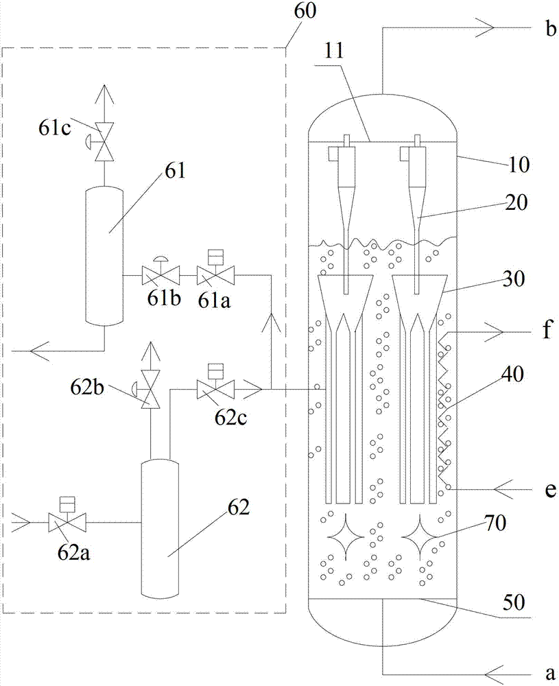
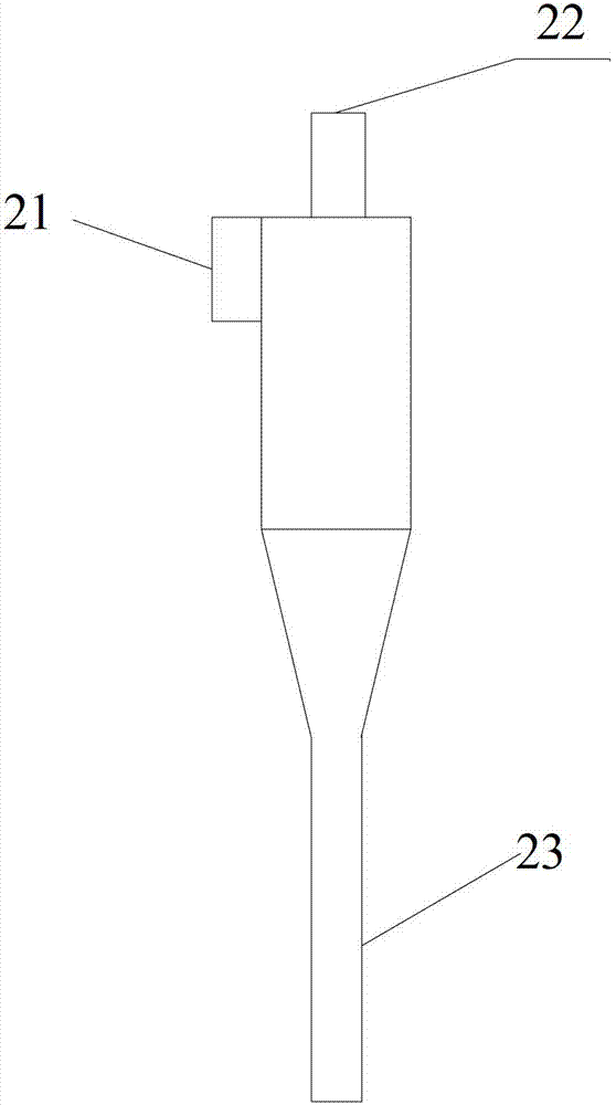
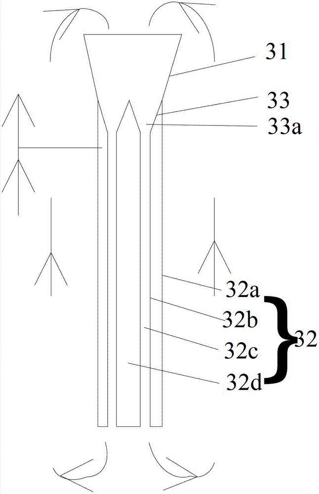
[0038] like figure 1As shown, the slurry bed reactor according to the present invention includes: a reactor cylinder 10, the bottom of the inner cavity of the reactor cylinder 10 is provided with a gas introduction device, and the inner cavity of the reactor cylinder 10 is provided with a Fischer-Tropsch Wax and catalyst separation device 30; the outside of reactor shell 10 is provided with and communicates with Fischer-Tropsch wax and catalyst separation device 30 to extract Fischer-Tropsch wax and Fischer-Tropsch wax and catalyst separation device 30 backwash Fischer-Tropsch wax extraction and reverse Blowing system 60 ; a gas-liquid separation device located above the Fischer-Tropsch wax and catalyst separation device 30 is also provided in the inner chamber of the reactor cylinder 10 . By installing a gas-liquid separation device on the top of the Fis...


PUM


Abstract

The invention provides a slurry bed reactor which comprises a reactor cylinder body, wherein a gas leading-in device is arranged at the lower part inside the inner chamber of the reactor cylinder body, a fischer-tropsch wax and catalyst separating device is arranged inside the inner chamber of the reactor cylinder body, a fischer-tropsch wax extracting and back flushing system communicated with the fischer-tropsch wax and catalyst separating device and used for extracting fischer-tropsch wax and back washing to the fischer-tropsch wax and catalyst separating device is arranged at the exterior of the reactor cylinder body; and a gas-liquid separation device positioned above the fischer-tropsch wax and catalyst separating device is further arranged inside the inner chamber of the reactor cylinder body. In the slurry bed reactor provided by the invention, through the arrangement of the gas-liquid separation device, gas flow entering the fischer-tropsch wax and catalyst separating device can be reduced, so that gas is effectively prevented from invading and occupying the surface of a filtration medium, and the effective surface of the filtration medium is improved. Meanwhile, the invention solves the problem of reduced permeability of the filtration medium, which is caused by the fact that catalyst particles are dried up on the filtration medium due to the situation that the gas dries the apertures of the filtration medium.

Description

technical field [0001] The invention relates to the field of Fischer-Tropsch synthesis, in particular to a slurry bed reactor. Background technique [0002] In recent years, the global crude oil price has gradually increased, especially in some countries rich in coal and short of oil, the development of non-petroleum energy technology has attracted extensive attention. Fischer-Tropsch synthesis refers to synthesis gas (H 2 +CO) under the action of a catalyst, under the appropriate reaction temperature and reaction pressure, the reaction process of synthesizing hydrocarbon liquid fuels and high value-added chemicals. Coal or natural gas is transformed into high-quality liquid fuels and high value-added chemicals through Fischer-Tropsch synthesis, which not only uses coal resources reasonably, efficiently and cleanly, but also makes up for the relative shortage of petroleum resources, making Fischer-Tropsch synthesis technology an alternative energy source for petroleum effi...

Claims


Application Information

Patent Timeline
Patent Type & Authority Patents(China)
IPC IPC(8): B01J8/22C07C1/04C10G2/00
Inventor 王洪学石玉林吕毅军门卓武卜亿峰李导
Owner CHNA ENERGY INVESTMENT CORP LTD
Learn More