
Pin shaft, mounting structure for pin shaft, and concrete pumping equipment

A technology for installing structures and pins, which is applied in building construction, processing of building materials, bolts, etc., and can solve problems such as inconvenient installation and disassembly, high labor intensity, and heavy pin weights

Active Publication Date: 2012-10-03
ZOOMLION HEAVY IND CO LTD
View PDF7 Cites 1 Cited by
  • Summary
  • Abstract
  • Description
  • Claims
  • Application Information

AI Technical Summary

Problems solved by technology

[0008] The present invention aims to provide a pin shaft, a pin shaft installation structure and concrete pumping equipment to solve the problems of heavy pin shaft weight, inconvenient installation and disassembly, high labor intensity and low yield strength in the prior art

Method used


Image

  • Pin shaft, mounting structure for pin shaft, and concrete pumping equipment
  • Pin shaft, mounting structure for pin shaft, and concrete pumping equipment
  • Pin shaft, mounting structure for pin shaft, and concrete pumping equipment

Examples


Embodiment Construction

[0044] The embodiments of the present invention will be described in detail below with reference to the accompanying drawings, but the present invention can be implemented in many different ways defined and covered by the claims.

[0045] Figure 4 show figure 1 The simply supported beam model of the pin axis in , and the corresponding relationship diagram of shear force and bending moment. in, figure 2 The structure shown can be simplified to Figure 4 In the simply supported beam shown in part (a), wherein, P is the load, the end of the simply supported beam is equivalent to the connecting rod 400', and the fulcrum between the two ends is equivalent to the sleeve seat 340'. further, Figure 4 (b) is the shear force diagram of the simply supported beam under the action of load P, and (c) is the bending moment diagram of the simply supported beam under the action of load P. Depend on Figure 4 It can be seen that the part L1 between the connecting rod 400' and the bushi...


PUM


Abstract

The invention provides a pin shaft, a mounting structure for the pin shaft, and concrete pumping equipment. The pin shaft comprises a body and shaft center parts, wherein the body comprises a cavity body; the cavity body is extended along the axial direction of the pin shaft, and comprises at least one end part which is arranged along the axial direction of the pin shaft; and the shaft center parts are arranged on the end parts. The shaft center parts of the pin shaft are used for resisting a shear load, and a part opposite to the cavity body is used for resisting a bending moment load, so that materials of the pin shaft are optimally distributed, and the aim of reducing the weight of the pin shaft is fulfilled. In addition, the pin shaft is hollow, so that the inner and outer surfaces of the pin shaft are fully hardened and tempered to strengthen the strength of the shaft center parts and the whole strength of the pin shaft.

Description

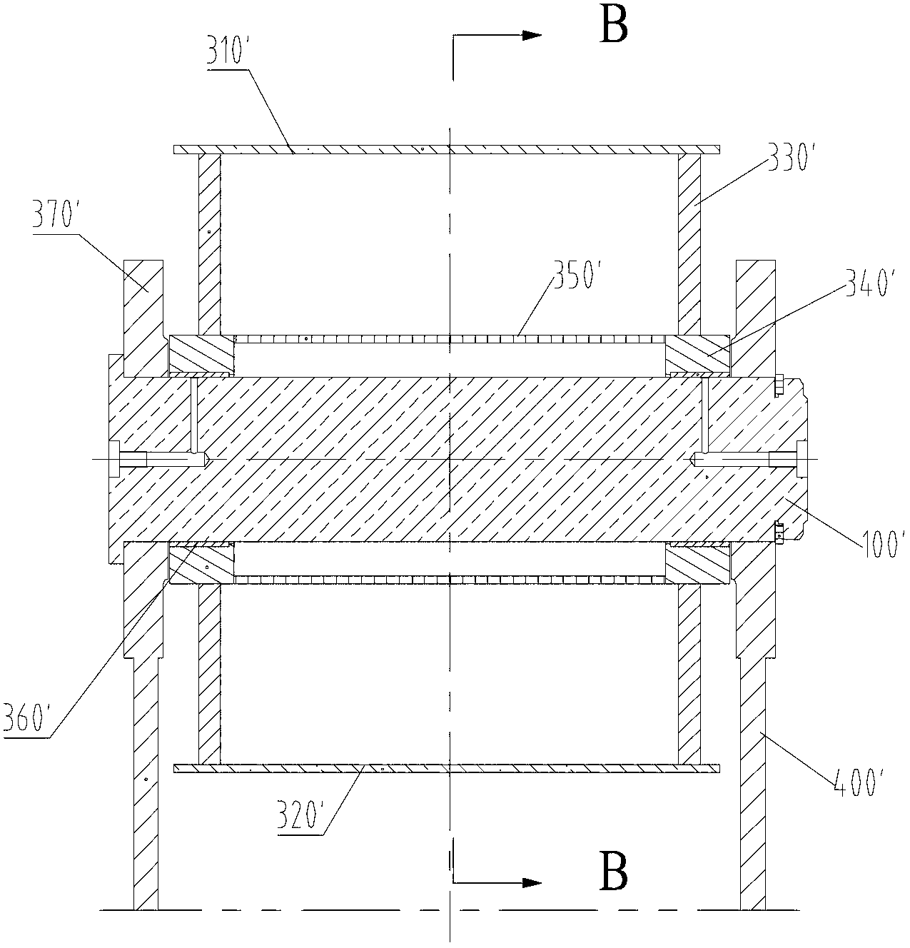
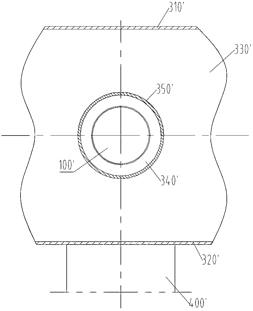
technical field [0001] The invention relates to the field of machinery, more specifically, to a pin shaft, a pin shaft installation structure and concrete pumping equipment. Background technique [0002] In the prior art, it is usually necessary to connect the two parts through pin shafts to transmit loads. The following takes the concrete pump truck and the boom of the concrete placing machine as examples to illustrate the connection method of the pin shaft. [0003] Such as figure 1 As shown, the boom includes a first section arm 200' and a second section arm 300', and the first section arm 200' and the second section arm 300' are connected by a pin shaft 100'. [0004] Such as Figure 1-3 As shown, the second joint arm 300' includes an upper cover plate 310', a lower cover plate 320', a web 330' and a sleeve seat 340'. The upper cover plate 310', the lower cover plate 320' and the web 330' form a packaged box shape, the bushing seat 340' is installed on the web 330', ...

Claims


Application Information

Patent Timeline
IPC IPC(8): F16B19/02E04G21/04
CPCE04G21/0445E04G21/0436E04G21/04F16B19/02
Inventor 李乡安邝昊黄柯余德海
Owner ZOOMLION HEAVY IND CO LTD
Learn More