Shared-channel electromagnetic pulse valve

A technology of electromagnetic pulse valve and electromagnetic pilot valve, which is applied in the direction of valve details, diaphragm valves, valve devices, etc., can solve the problems affecting the opening speed of pulse valves, and achieve the effect of improving the closing and opening speed

Inactive Publication Date: 2012-10-03
SHANGHAI SHANGTAI ENVIRONMENTAL COMPONENTS
View PDF6 Cites 3 Cited by
  • Summary
  • Abstract
  • Description
  • Claims
  • Application Information

AI Technical Summary

Problems solved by technology

It can be seen that the large diameter of the orifice 3 can increase the closing speed of the pulse valve, but it affects the opening speed of the pulse valve and becomes the main obstacle to improving the opening and closing speed of the pulse valve.

Method used


Image

  • Shared-channel electromagnetic pulse valve
  • Shared-channel electromagnetic pulse valve
  • Shared-channel electromagnetic pulse valve

Examples


Embodiment Construction

[0017] In order to make the present invention more comprehensible, preferred embodiments are described in detail below with accompanying drawings.

[0018] The shared channel structure proposed by the present invention can be applied to both the diaphragm type electromagnetic pulse valve and the valve type electromagnetic pulse valve. The invention will be described in detail below taking the diaphragm type electromagnetic pulse valve as an example.

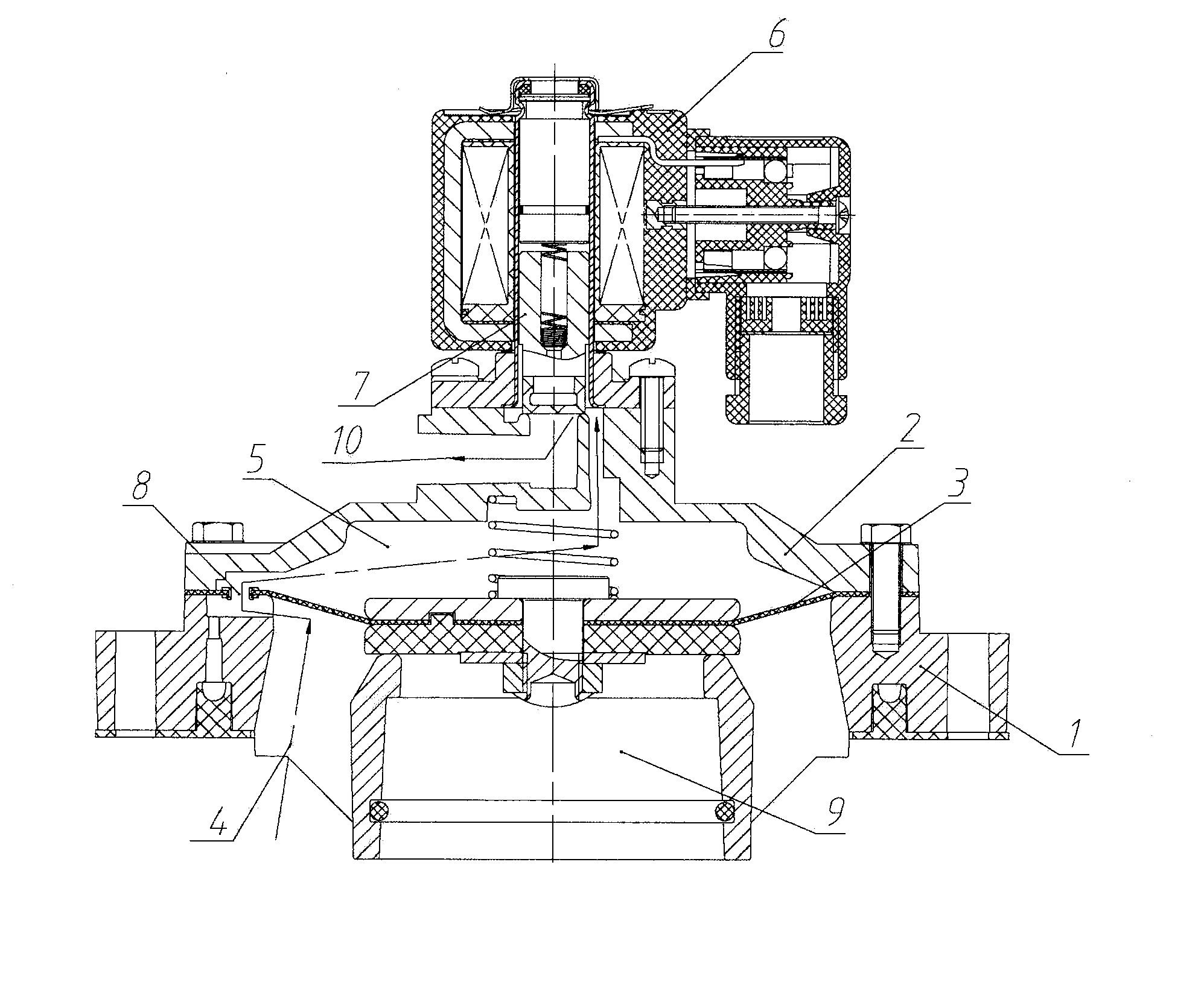
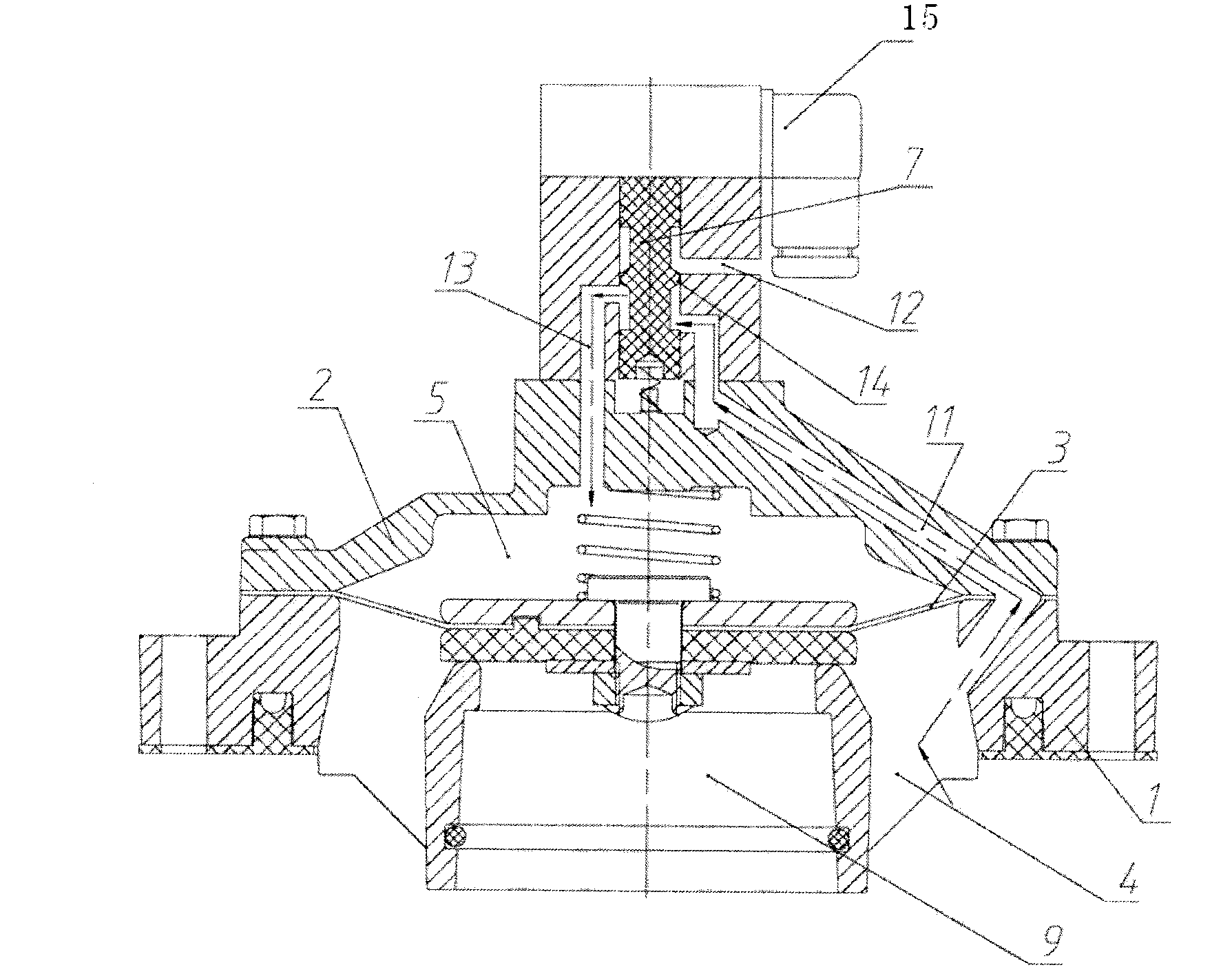
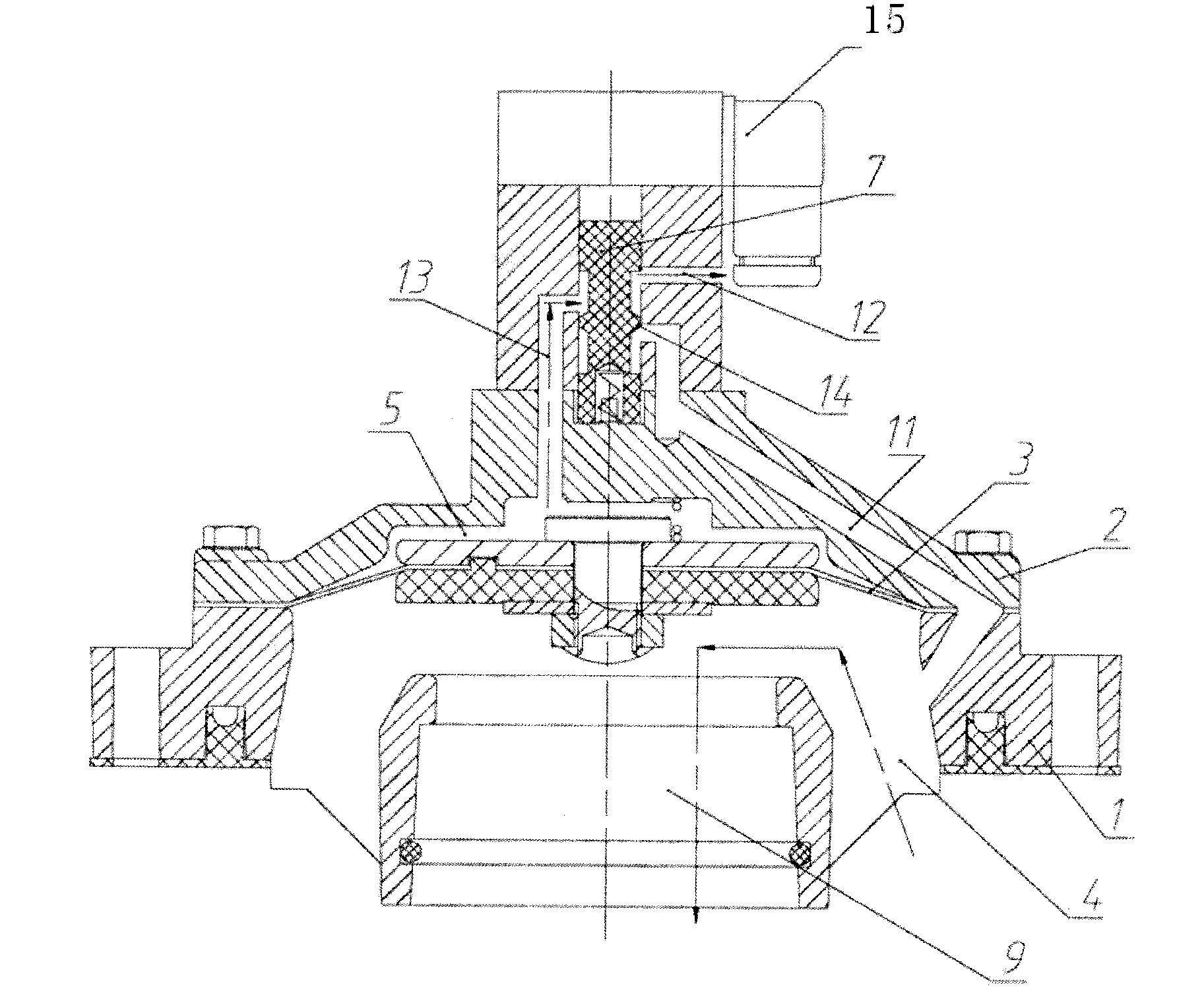
[0019] Such as figure 2 and image 3 As shown, a common channel electromagnetic pulse valve disclosed in this embodiment includes a valve body 1, an output port 9 is provided in the valve body 1, a valve cover 2 is provided on the valve body 1, and the diaphragm 3 will be located at the The air cavity in the valve body 1 and the valve cover 2 is divided into a front air chamber 4 and a rear air chamber 5. An electromagnetic pilot valve 15 is arranged on the valve cover 2, and a valve core 7 is arranged inside the electromagneti...


PUM


Abstract

The invention provides a shared-channel electromagnetic pulse valve which comprises a valve body and is characterized in that a gas inlet channel and a shared channel are arranged in the valve body, a valve cap and an electromagnetic pilot valve; the inlet end of the gas inlet channel is communicated with a front gas chamber, and the outlet end of the gas inlet channel is positioned at the inner wall of the electromagnetic pilot valve; one end of the shared channel is positioned on the inner wall of the electromagnetic pilot valve, and the other end of the shared channel is communicated with a rear gas chamber; an exhaust channel is arranged in the electromagnetic pilot valve; the inlet end and the outlet end of the exhaust channel are respectively positioned on the inner wall and the outer edge of the electromagnetic pilot valve; and a circle of annular bulge is formed on the outer edge of a valve core. According to the invention, the closing time is determined by the gas inlet channel, and the opening time is determined by the exhaust channel, so that the contradictory caused by a throttle orifice in the traditional electromagnetic pulse valve is solved, and the closing speed and the opening speed of the electromagnetic pulse valve are greatly increased.

Description

technical field [0001] The invention relates to an electromagnetic pulse valve. Background technique [0002] The electromagnetic pulse valve is a device for generating the dust-cleaning airflow of the pulse-jet bag filter. Its working principle is to use the pressure change of the two air chambers before and after the diaphragm to realize the opening and closing of the pulse valve. [0003] The existing electromagnetic pulse valve structure is usually as follows figure 1 As shown, including the valve body 1, an output port 9 is provided in the valve body 1, and a valve cover 2 is provided on the valve body 1, and the air chamber located in the valve body 1 and the valve cover 2 is divided into front and rear The air chamber 4 and the rear air chamber 5 are provided with an orifice 8 on the diaphragm 3 , and an electromagnetic pilot 6 is provided on the valve cover 2 , and a moving iron core 7 is arranged inside the electromagnetic pilot 6 . Its working process is: when th...

Claims


Application Information

Patent Timeline
IPC IPC(8): F16K7/17F16K31/126B01D46/42
Inventor 朱德生
Owner SHANGHAI SHANGTAI ENVIRONMENTAL COMPONENTS
Why Eureka
Try Eureka