
Pressure and headloss maintaining valve system for clean and dirty water systems

a technology of pressure and headloss, which is applied in the direction of actuators, servomotors, actuator accumulators, etc., can solve the problems of system inoperableness and springs that significantly increase the pressure for operating the valve, and achieve the effect of increasing the closing speed of the valv

Active Publication Date: 2020-04-21
RED VALVE
View PDF10 Cites 0 Cited by
  • Summary
  • Abstract
  • Description
  • Claims
  • Application Information

AI Technical Summary

Benefits of technology

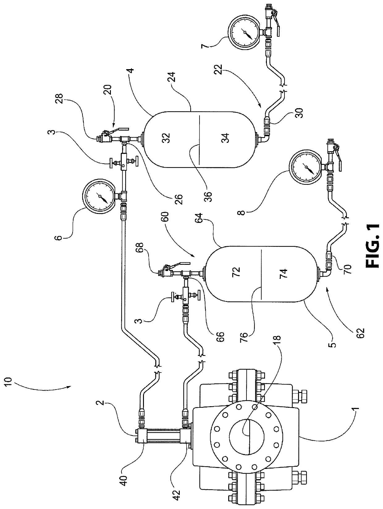
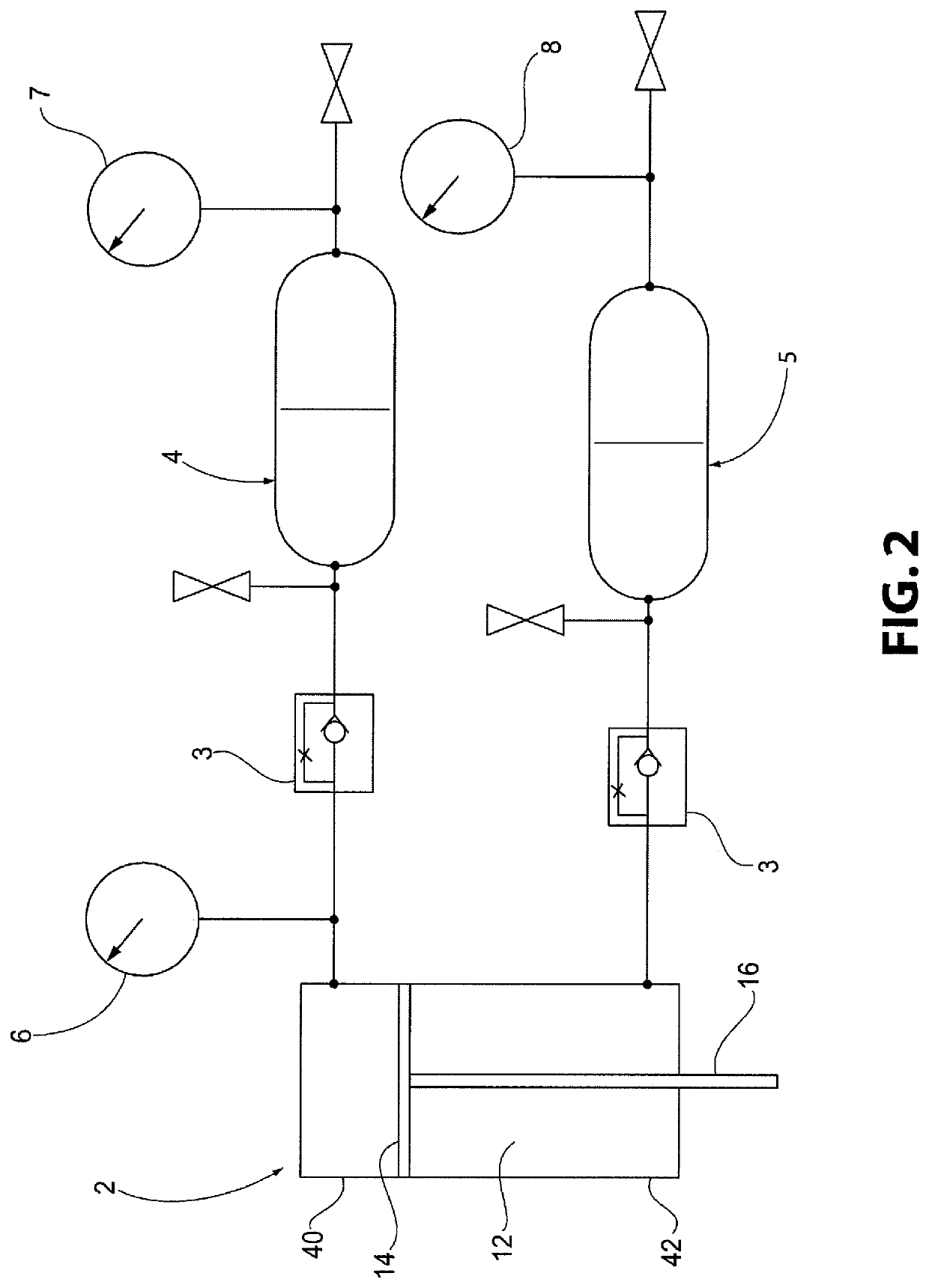
The present invention provides a valve system with a first accumulator and a second accumulator. The second accumulator helps to increase the closing speed of the valve. This system can be used in industrial or manufacturing processes to improve the speed and efficiency of the valve closing process.

Problems solved by technology

While these approaches are able to maintain pressure in the pipelines, they have various drawbacks.
Further, the use of internal fluid pressure to directly and intimately effect operation will cause the system to become inoperable if the liquid is dirty or creates deposits that clog the passageways and diaphragms.
Springs could also be used; however, springs significantly increase the pressure for operating the valve as the springs become compressed and exert more force.

Method used


Image

  • Pressure and headloss maintaining valve system for clean and dirty water systems
  • Pressure and headloss maintaining valve system for clean and dirty water systems

Examples


Embodiment Construction

[0041]For purposes of the following detailed description, it is to be understood that the invention may assume various alternative variations and step sequences, except where expressly specified to the contrary. Moreover, other than in any operating examples, or where otherwise indicated, all numbers expressing, for example, quantities of ingredients used in the specification and claims are to be understood as being modified in all instances by the term “about”. Accordingly, unless indicated to the contrary, the numerical parameters set forth in the following specification and attached claims are approximations that may vary depending upon the desired properties to be obtained by the present invention. At the very least, and not as an attempt to limit the application of the doctrine of equivalents to the scope of the claims, each numerical parameter should at least be construed in light of the number of reported significant digits and by applying ordinary rounding techniques.

[0042]N...


PUM


Abstract

A valve system includes: a valve; a hydraulic cylinder attached to at least a portion of the valve; and at least a first accumulator in fluid communication with the hydraulic cylinder. The first accumulator includes: (i) a first end having a fluid inlet and a fluid outlet; (ii) a second end having a gas inlet; and (iii) a body positioned between the first end and the second end and which includes a fluid chamber and a gas chamber separated by a flexible separating member. The hydraulic cylinder is configured to close the valve in response to pressure provided by fluid distributed from the first accumulator.

Description

CROSS REFERENCE TO RELATED APPLICATION[0001]This application claims the benefit of U.S. Provisional Application No. 62 / 383,865, filed Sep. 6, 2016, which is incorporated herein by reference in its entirety.BACKGROUND OF THE INVENTION[0002]Field of the Invention[0003]The present invention is directed to valves for water systems, and, in particular, to valve systems for maintaining pressure and headloss in pipelines.[0004]Description of Related Art[0005]Water systems generally require valves that are capable of maintaining a pressure in the pipelines. This is typically achieved by using a pressure sensor linked to a control valve, or by using the internal fluid pressure in the pipeline to enter a series of pressure balanced diaphragms within the valve. While these approaches are able to maintain pressure in the pipelines, they have various drawbacks. For instance, the control valve linked to the pressure sensor requires an external power source to actuate the valve. Further, the use o...

Claims


Application Information

Patent Timeline
Patent Type & Authority Patents(United States)
IPC IPC(8): F16L55/053F15B11/10F15B1/08
CPCF15B11/10F15B1/08F16L55/053F15B2201/205F15B2211/27F15B2201/411F15B2201/51F15B2201/4155F15B2211/7053F15B2211/212
Inventor PLATUSICH, BRUCE M.
Owner RED VALVE
Learn More