Valve capable of being opened and closed effortlessly
A valve and switch technology, which is applied in the field of labor-saving valves, can solve the problems of labor-intensive use of valves, and achieve the effects of avoiding secondary pollution, avoiding resistance, and reducing difficulty in use
- Summary
- Abstract
- Description
- Claims
- Application Information
AI Technical Summary
Problems solved by technology
Method used
Image
Examples
Embodiment 1
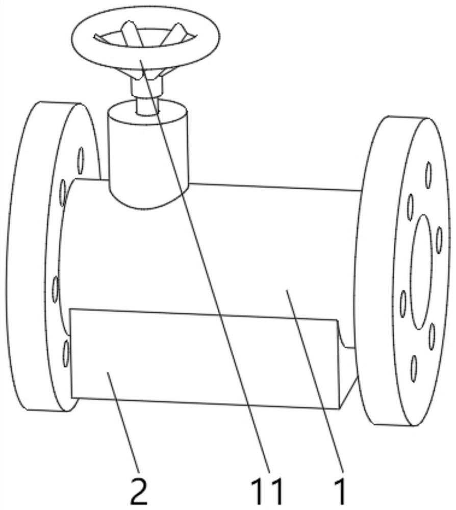
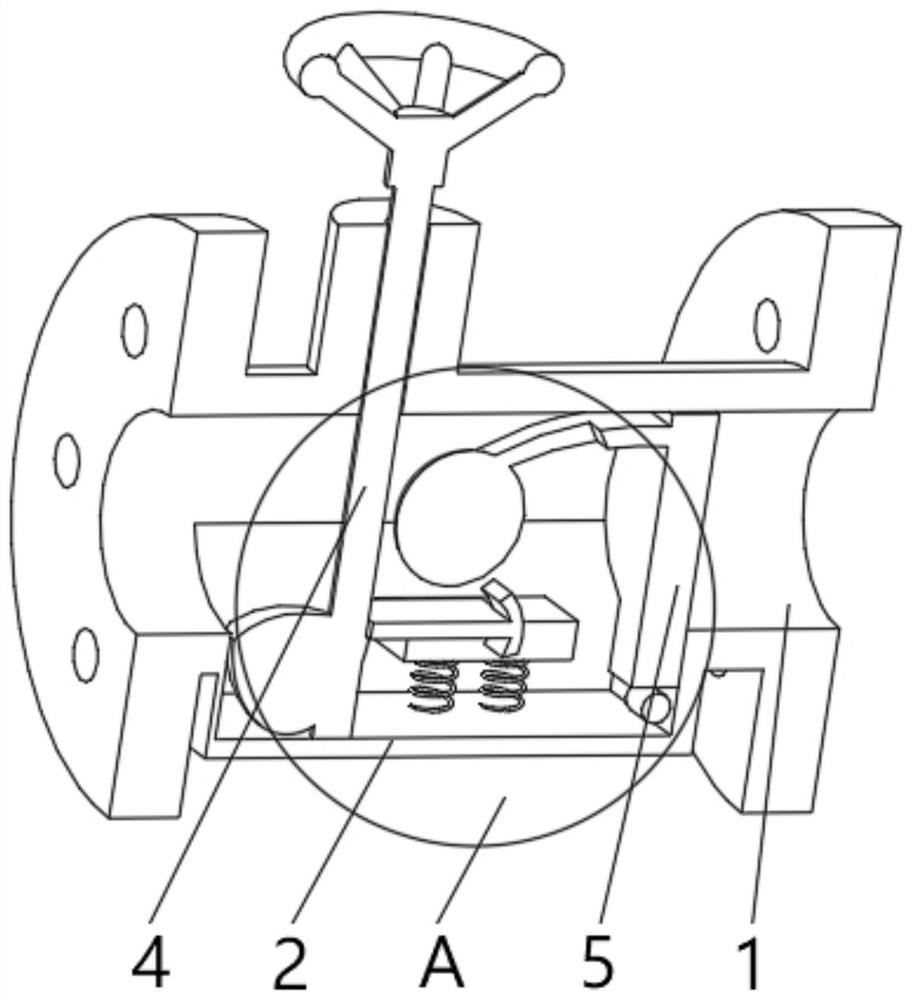
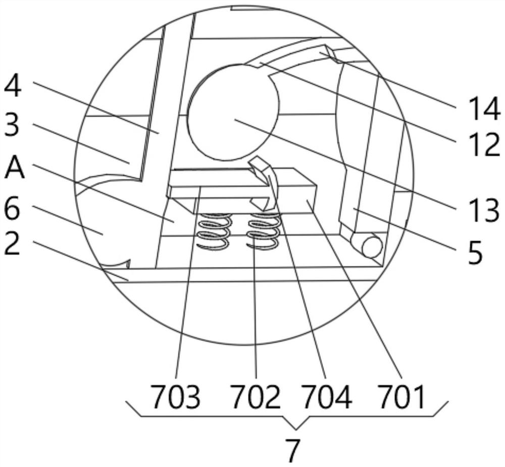
[0029] see Figure 1-3 , the present invention provides a technical solution: a switch labor-saving valve, including a valve body 1, the bottom of the valve body 1 is fixedly connected with an expansion block 2, the inner bottom of the valve body 1 is provided with an expansion slot 3, and the expansion slot 3 runs through the expansion block 2 and extend to the inside of the expansion block 2, the valve stem 4 is installed on the top of the valve body 1, the valve stem 4 runs through the valve body 1 and extends to the inside of the expansion slot 3, the top of the valve stem 4 is fixedly connected with a handle 11, the expansion slot One side of the inner wall of 3 is rotatably connected with a sealing cover plate 5 that is compatible with the valve body 1, and one end of the valve stem 4 located inside the expansion groove 3 is fixedly connected with a semicircular bump 6, and the inside of the expansion groove 3 is close to the semicircular bump 6. The position is equipped...
Embodiment 2
[0034] see Figure 1-4, the present invention provides a technical solution: on the basis of Embodiment 1, an oscillating device 8 is installed on the top of the semicircular bump 6, the oscillating device 8 includes a hydraulic plate 801, the hydraulic plate 801 is slidingly connected with the semicircular bump 6, and the valve stem The outer side of 4 is provided with a lifting ring 802, and a control rod 803 is rotatably connected between the lifting ring 802 and the semicircular protrusion 6, and the top of the hydraulic plate 801 is rotatably connected to the control rod 803, and the outer side of the valve stem 4 is located below the lifting ring 802 The shock rod 804 is evenly installed, and the end of the shock rod 804 away from the valve rod 4 is fixedly connected with a knocking ball 805, and the overall density of the knocking ball 805 is smaller than that of water.
[0035] When in use, the water flow passing through the valve body 1 drives the hydraulic plate 801 ...
Embodiment 3
[0037] see Figure 1-6 , the present invention provides a technical solution: on the basis of Embodiment 1, an extension groove 9 is provided on the side of the semicircular protrusion 6 away from the valve stem 4, and an extrapolation device 10 is installed inside the extension groove 9, and the extrapolation device 10 Including a rubber membrane 101, one end of the rubber membrane 101 is symmetrically installed with an extension strip 102, and the end of the extension strip 102 away from the rubber membrane 101 is fixedly connected with the extension groove 9, and the inner wall side of the extension groove 9 is fixedly connected with an outer pushing ball through an elastic plate 103 104 , the push-out ball 104 is in sliding connection with the rubber membrane 101 .
[0038] Metal soft strips 15 are symmetrically installed on the outside of the rubber membrane 101 , and a magnet block 16 is symmetrically installed on the end of the rubber membrane 101 extending to the outsi...
PUM
 Abstract
Description
Claims
Application Information
 - R&D
- Intellectual Property
- Life Sciences
- Materials
- Tech Scout
- Unparalleled Data Quality
- Higher Quality Content
- 60% Fewer Hallucinations
Browse by: Latest US Patents, China's latest patents, Technical Efficacy Thesaurus, Application Domain, Technology Topic, Popular Technical Reports.
© 2025 PatSnap. All rights reserved.Legal|Privacy policy|Modern Slavery Act Transparency Statement|Sitemap|About US| Contact US: help@patsnap.com


