Pulverized coal burner

A pulverized coal burner and pulverized coal technology are applied in the direction of burners, burners for burning powder fuel, and combustion methods, etc., which can solve the problems of high thermal power of igniters, potential safety hazards, waste of resources, etc., and achieve reduction of thermal power, The effect of preventing deflagration and avoiding waste

Active Publication Date: 2012-10-03
CHNA ENERGY INVESTMENT CORP LTD +1
View PDF6 Cites 12 Cited by
  • Summary
  • Abstract
  • Description
  • Claims
  • Application Information

AI Technical Summary

Problems solved by technology

At present, during the operation of the pulverized coal burner, the amount of ignition oil is very considerable. Under unfavorable working conditions (such as poor coal quality, low load, abnormal coal supply, etc.), it is necessary to add fuel to support combustion, resulting in the heat of the igniter The power accounts for a large proportion of the total thermal power of the burner (mostly about 10%), and the thermal power of the igniter with other functions (such as stable combustion, low-load combustion, etc.) accounts for the proportion of the total thermal power of the burner. Larger (up to 20% to 30%), resulting in a waste of resources
In addition, due to the excessive thermal power of the igniter, it is easy to cause deflagration, which brings safety hazards

Method used


Image

  • Pulverized coal burner
  • Pulverized coal burner
  • Pulverized coal burner

Examples


Embodiment approach

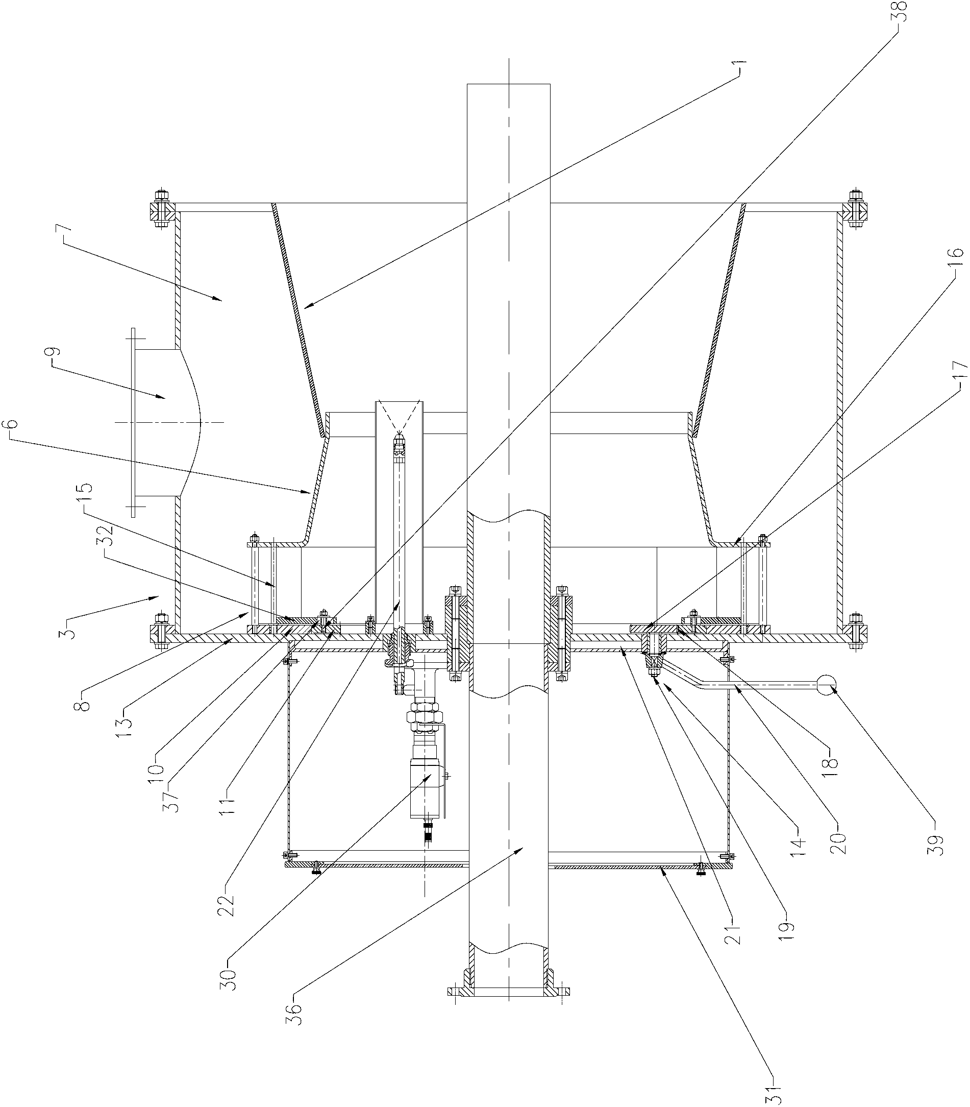
[0053] According to a preferred embodiment of the present invention, the end plate 13 is provided with a water-cooled interlayer 21 . In this way, the sensors and electrical components inserted through the end plate 13 can be cooled through the water-cooling interlayer 21 to prevent them from being damaged.

[0054] The igniter 22 can take various suitable configurations. According to a preferred embodiment of the present invention, the igniter 22 includes an ignition air gun 23 and an oil gun 24 . In this way, the liquefied gas can be ignited by the ignition air gun 23 first, and after the liquefied gas is ignited, the oil gun 24 is sprayed, and the secondary flame is co-combusted in the pre-combustion chamber 1 under the condition of swirling air distribution, and the flame is full of the entire pre-combustion chamber. Room 1 starts to supply pulverized coal when the conditions are ripe. In this way, the two-stage ignition technology of gas and oil is adopted, and the igni...


PUM


Abstract

The invention provides a pulverized coal burner which comprises a prechamber (1), a hearth (2) and an air supply unit (3) supplying air to the prechamber (1), wherein an outlet end of the prechamber (1) is communicated with the hearth (2), and a flame lighter (22) and a pulverized coal jetting pipe (36) are inserted into the prechamber (1). According to the pulverized coal burner provided by the invention, the lighting and the burning can be carried out grade by grade, and can be preferably controlled. Furthermore, the pulverized coal in the prechamber is higher in concentration, so that the flame can not be blown out by combustion air, the stable combustion can be realized, the pulverized coal airflow can be ignited by less igniting energy, the hot power of the igniter can be reduced, the resources waste can be avoided, the detonation can be avoided, and the safety performance can be improved.

Description

technical field [0001] The invention relates to a pulverized coal burner. Background technique [0002] In power stations, most medium-capacity pulverized coal burners adopt a multi-stage ignition method. The igniter ignites gas fuel, liquid fuel or pulverized coal step by step, and then ignites pulverized coal and the furnace. At present, during the operation of the pulverized coal burner, the amount of ignition oil is very considerable. Under unfavorable working conditions (such as poor coal quality, low load, abnormal coal supply, etc.), it is necessary to add fuel to support combustion, resulting in the heat of the igniter The power accounts for a large proportion of the total thermal power of the burner (mostly about 10%), and the thermal power of the igniter with other functions (such as stable combustion, low-load combustion, etc.) accounts for the proportion of the total thermal power of the burner. Larger (up to 20% to 30%), resulting in a waste of resources. In a...

Claims


Application Information

Patent Timeline
Patent Type & Authority Applications(China)
IPC IPC(8): F23D1/02
Inventor 仝胜录王晓雷麻林霍卫东杜铭华郭治杜万斗
Owner CHNA ENERGY INVESTMENT CORP LTD
Why Eureka
Try Eureka