Movement limiting device for lamp and moving lamp

A limit device and motion technology, applied in lighting devices, use feedback control, gas/waterproof devices, etc., can solve the problems of no protection, single limit protection, lamp damage, etc., to achieve good waterproof effect, increase in size The effect of running load

Inactive Publication Date: 2012-10-03
OCEANS KING LIGHTING SCI&TECH CO LTD +1
View PDF6 Cites 4 Cited by
  • Summary
  • Abstract
  • Description
  • Claims
  • Application Information

AI Technical Summary

Problems solved by technology

When the existing lamp movement structure rotates, the limit position is mostly protected by a single limit, and some even have no protection at all, which can easily lead to damage to the lamp

Method used


Image

  • Movement limiting device for lamp and moving lamp
  • Movement limiting device for lamp and moving lamp
  • Movement limiting device for lamp and moving lamp

Examples


Embodiment 1

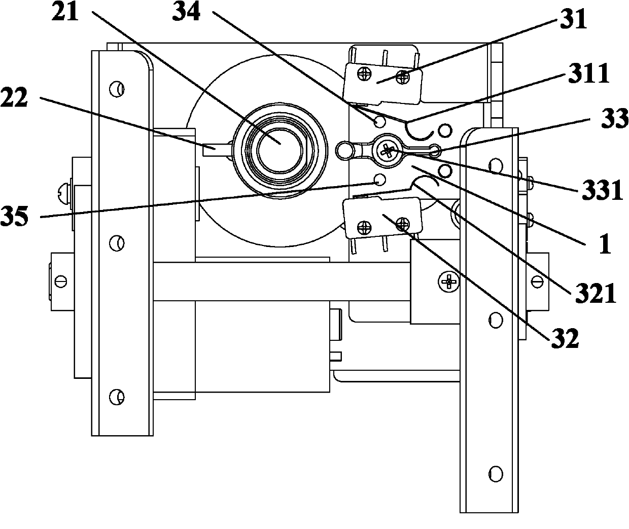
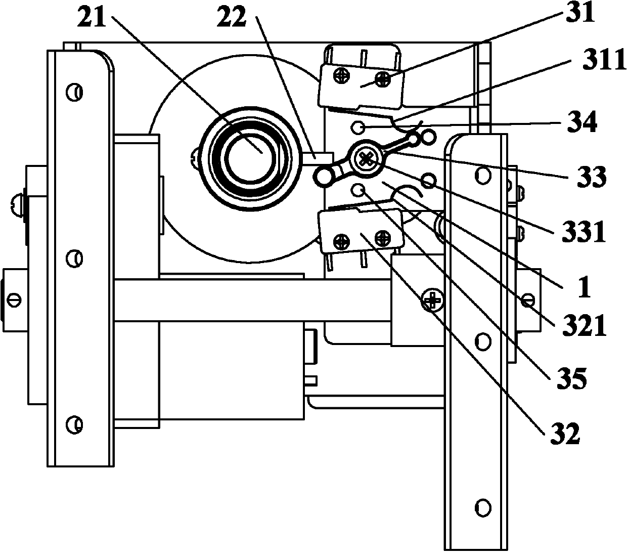
[0035] like figure 1 and figure 2 As shown, the first limiting unit includes a fixed plate 1 , a first rotating assembly 2 and a first limiting assembly 3 . The first rotating assembly 2 and the first limiting assembly 3 are arranged on the fixed plate 1 .

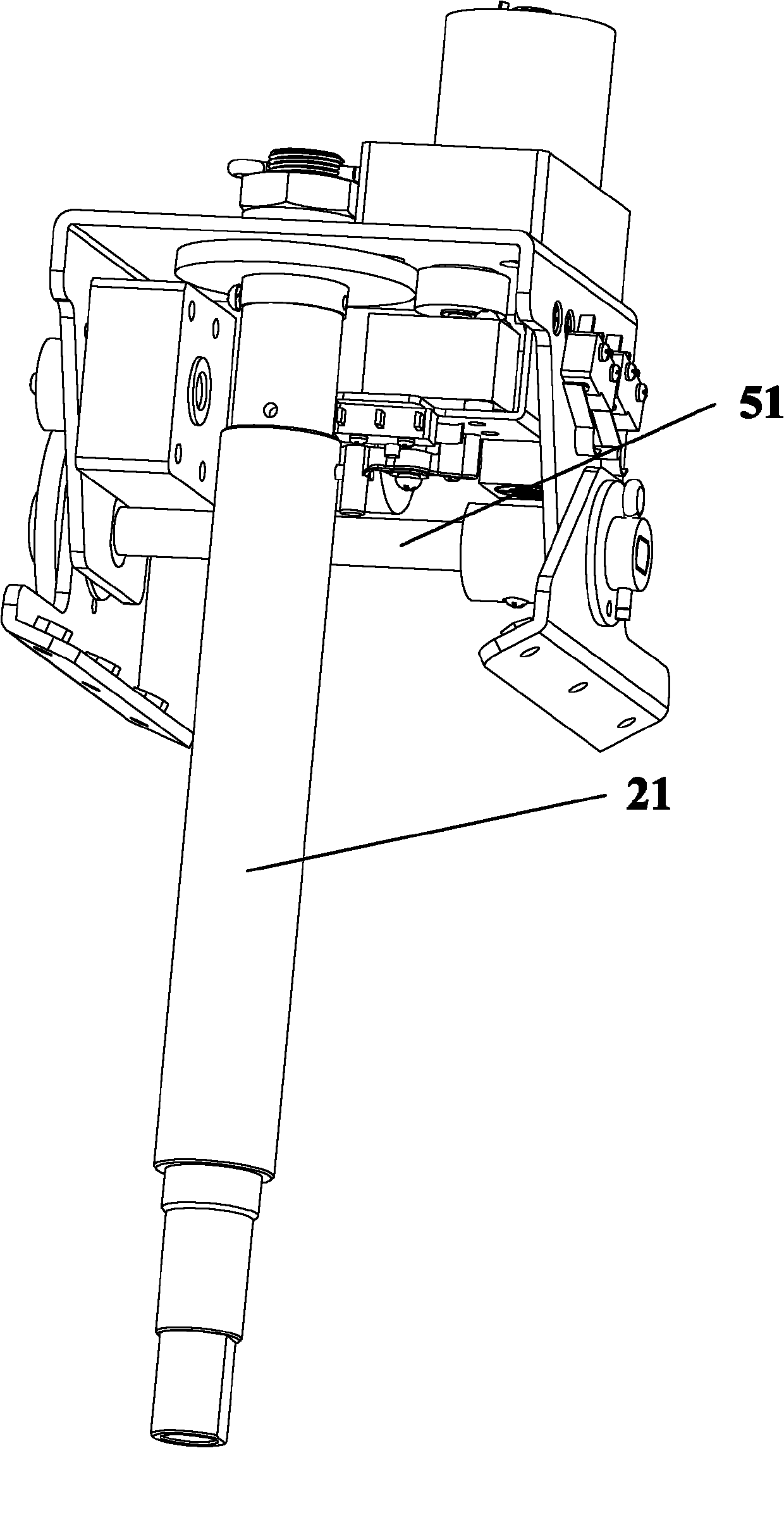
[0036] The first rotating assembly 2 includes a first motor, a main shaft 21 and a pole 22 . The support rod 22 is fixed on the outside of the main shaft 21 , the first motor can drive the main shaft 21 to rotate, and the support rod 22 rotates synchronously with the main shaft 21 .

[0037] The first limit assembly 3 includes a first switch 31 , a second switch 32 , a shift lever 33 , a shift lever shaft 331 , a first shift leg 34 and a second shift leg 35 . The driving lever 33 is connected to the fixed plate 1 through the driving lever rotating shaft 331, and the driving lever 33 can rotate around the driving lever rotating shaft 331; the first gear leg 34 and the second gear leg 35 are symmetrically fixed on both s...

Embodiment 2

[0053] like Figure 8 and Figure 9 As shown, the motion lamp 100 includes a base 110 and a lampshade 120; it also includes the movement limiting device described in Embodiment 1, one end of the movement limiting device is connected to the base 110 through the main shaft 21, and the other end is fixed in the lampshade 120, so that the The first limiting unit is used to limit the movement of the lampshade 120 in the horizontal direction, and the second limiting unit is used to limit the movement of the lampshade 120 in the vertical direction.

[0054] Wherein, the light source equipment is installed on the movement limiting device and located inside the lampshade 120 .

[0055] preferred, such as Figure 10 As shown, it also includes a seal 130 and a waterproof bearing 140; the inner ring of the waterproof bearing 140 is tightly fitted on the end where the main shaft is connected to the base, and the outer ring of the waterproof bearing is connected to one end of the seal 130...


PUM


Abstract

The invention discloses a movement limiting device for a lamp. The movement limiting device comprises a first limiting unit and a second limiting unit. The invention further provides a lamp containing the movement limiting device. The movement limiting device has the beneficial effects: when a lamp moving structure rotates to a limit position, a limiting protection device for switching off a power supply of a motor to stop the motor from running through a touch switch elastic sheet is adopted; and a gear supporting leg is arranged and is used for stopping a shifting rod or a bracket from rotating when a switch is damaged, so that the operating load of the motor is increased, the motor is stopped from rotating by using the overload protection of the motor, and the moving lamp is protected. The movement limiting device can be used for preventing the lamp from being damaged easily.

Description

technical field [0001] The invention relates to the technical field of lighting components, in particular to a motion limiting device for a lamp and a motion lamp using the device. Background technique [0002] The moving structure of the luminaire is usually set with a certain limit protection at the extreme position of the moving structure for the sake of protecting the luminaire. When the existing lamp movement structure rotates, the limit position is mostly protected by a single limit, and some even have no protection at all, which can easily lead to damage to the lamp. Contents of the invention [0003] The invention discloses a motion limiting device for a lamp, which aims to provide multi-layer limit protection for the lamp when it rotates, so as to protect the moving lamp from damage. [0004] To achieve the object of the present invention, the motion limiting device for a lamp of the present invention includes a first limiting unit. The first limiting unit inclu...

Claims


Application Information

Patent Timeline
Patent Type & Authority Applications(China)
IPC IPC(8): G05D3/12F21V31/00
Inventor 周明杰齐增智
Owner OCEANS KING LIGHTING SCI&TECH CO LTD
Why Eureka
Try Eureka