Thermal overload relay with current transformers

A thermal overload relay, current transformer technology, applied in circuits, electrical components, parts of protection switches, etc., to prevent electric shock hazards and avoid the effect of heat

Active Publication Date: 2014-09-10
SHANGHAI NOARK ELECTRIC
View PDF5 Cites 0 Cited by
  • Summary
  • Abstract
  • Description
  • Claims
  • Application Information

AI Technical Summary

Problems solved by technology

[0004] The purpose of the present invention is to provide a thermal overload relay with a current transformer that overcomes the above defects. By integrating the thermal release and the current transformer into a thermal overload relay with a current transformer, it not only solves the above three problems. There are many hidden dangers, and it has the comprehensive advantages of more compact and reasonable structure, easy installation and debugging, easy operation and use, and reduced product volume.

Method used


Image

  • Thermal overload relay with current transformers
  • Thermal overload relay with current transformers
  • Thermal overload relay with current transformers

Examples


Embodiment Construction

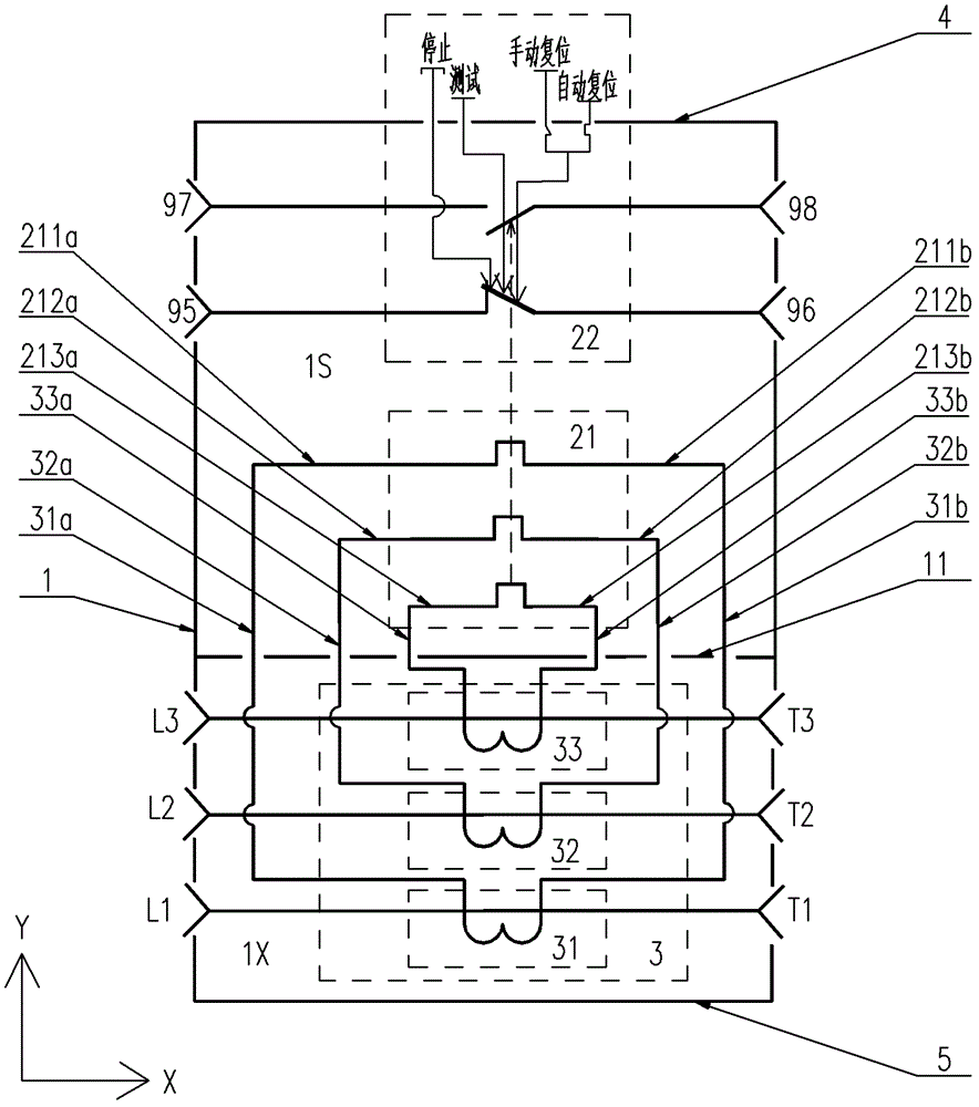
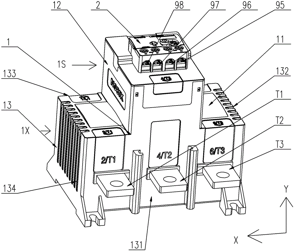
[0029] The following is attached Figure 1-11 Several specific implementations of the thermal overload relay with current transformer of the present invention are described in detail, wherein Figure 1-8 Can be generally used in the first embodiment or the second embodiment of the thermal overload relay with current transformer of the present invention, and Figure 9-11 It is only applicable to the first embodiment of the thermal overload relay with current transformer of the present invention. The current transformer of the first embodiment is arranged in a zigzag shape, and the current transformer of the second embodiment is arranged in a zigzag shape (not shown in the drawings). out). The thermal overload relay with current transformer of the present invention is not limited to the description of the following embodiments.

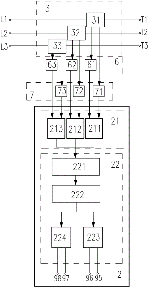
[0030] figure 1 It is a functional block diagram of the thermal overload relay with current transformer of the present invention, in which the conne...


PUM


Abstract

Thermal overload relay with current transformer, its overall double-layer shell is composed of horizontally stretched partition seat and longitudinally stretched barrel-shaped upper and lower shell walls, the thermal release is installed in the upper cavity, and the three current transformers are installed in the In the lower cavity, the two secondary lead wires of each current transformer enter the upper cavity from the lower cavity through the through hole provided at the joint intersection of the partition seat and the upper and lower cavity. The relay also includes L and T-side wiring devices arranged in the upper cavity, the L-side lead wire of each electric heating device is connected to the first lead wire of the corresponding current transformer through the L-side wiring assembly, and the T-side lead wire is connected to the corresponding current transformer through the T-side wiring assembly. The other lead of the current transformer is connected. The relay panel is fixedly connected to the barrel-shaped upper shell wall, and all devices and their leads are enclosed in the upper cavity, only the terminals protrude out of the upper cavity through the window on the panel, and the bottom plate is used to seal all the current transformer components in the double In the lower cavity of the layer shell.

Description

technical field [0001] The invention relates to a thermal overload relay, in particular to a thermal double gold overload relay with a current transformer. Background technique [0002] Thermal overload relay, referred to as thermal relay or thermal tripper, is a low-voltage electrical appliance widely used in overload protection of electric loads or AC motors, and can also be combined with a contactor to form an electromagnetic starter. Thermal bimetallic overload relay is the most commonly used thermal relay. It uses a bimetal sheet with delay characteristics as a thermal element. It not only has the function of overload protection, but also has the function of phase failure protection. The gold piece is connected in series to the line on the input side of the load such as the motor. When the motor is overloaded or a phase failure occurs in the three-phase line, the current of at least one phase line will increase, so that the double gold piece connected to the phase line ...

Claims


Application Information

Patent Timeline
Patent Type & Authority Patents(China)
IPC IPC(8): H01H71/14H01H71/02
Inventor 何化敏李伟
Owner SHANGHAI NOARK ELECTRIC
Why Eureka
Try Eureka