
Push rod type wafer clamping device employing stretching of cotton rope and springs

A clamping device and push rod type technology, applied in the field of wafer clamping devices, can solve the problems of wafer diameter size limitation, no limitation of vertical freedom degree, etc., and achieve the effect of avoiding wafer damage

Active Publication Date: 2015-02-18
TSINGHUA UNIV
View PDF3 Cites 0 Cited by
  • Summary
  • Abstract
  • Description
  • Claims
  • Application Information

AI Technical Summary

Problems solved by technology

[0006] ①The clamp 128, the protruding part 140, and the protruding part 6 are cylindrical. When fixing the wafer, only the degree of freedom in the horizontal direction of the wafer is limited, and the degree of freedom in the vertical direction is not restricted, so the wafer can only be transported in the horizontal plane;
[0008] ③ The positions of the raised supports 126 and 10 on the tray are fixed, so only a certain size range of wafers can be transported, limited by the diameter of the wafers

Method used


Image

  • Push rod type wafer clamping device employing stretching of cotton rope and springs
  • Push rod type wafer clamping device employing stretching of cotton rope and springs
  • Push rod type wafer clamping device employing stretching of cotton rope and springs

Examples


Embodiment Construction

[0039] The embodiments of the present invention will be further described in detail below in conjunction with the accompanying drawings.

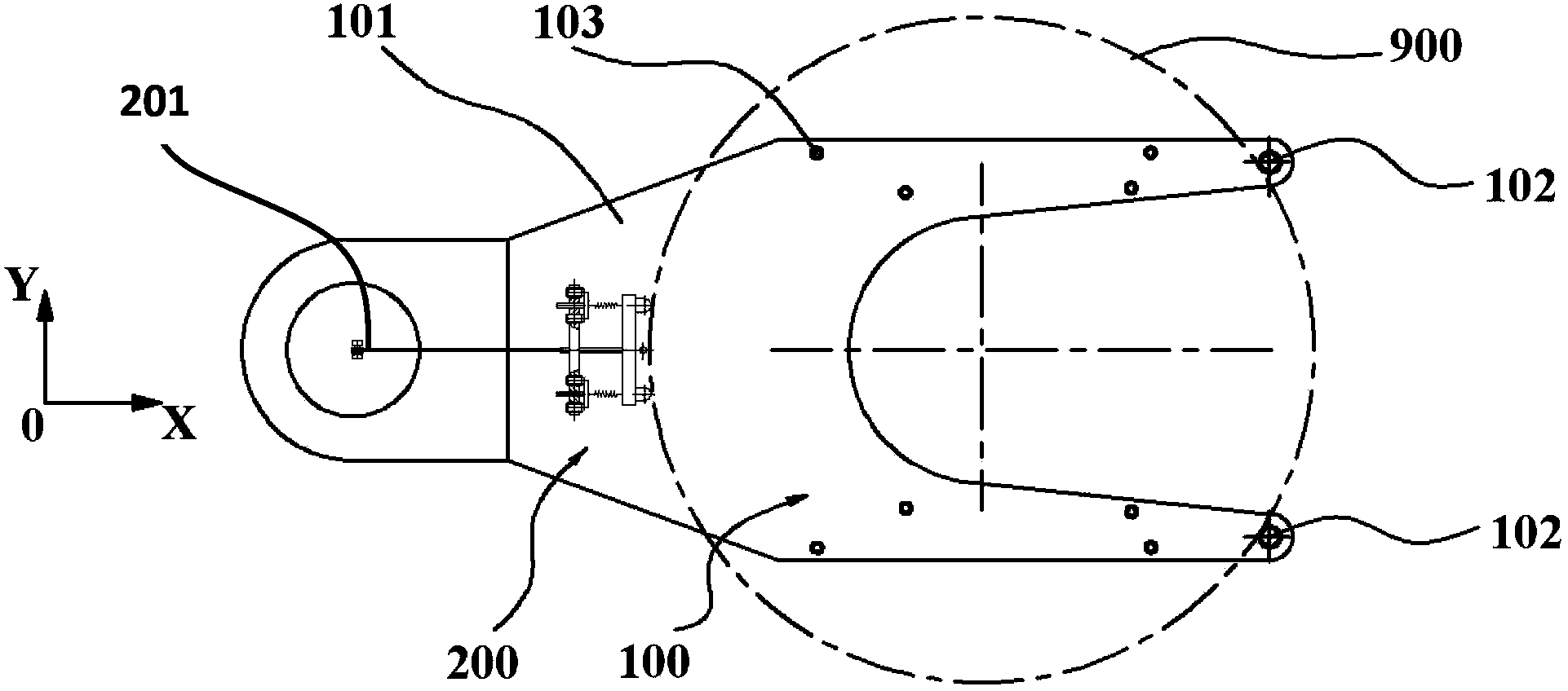
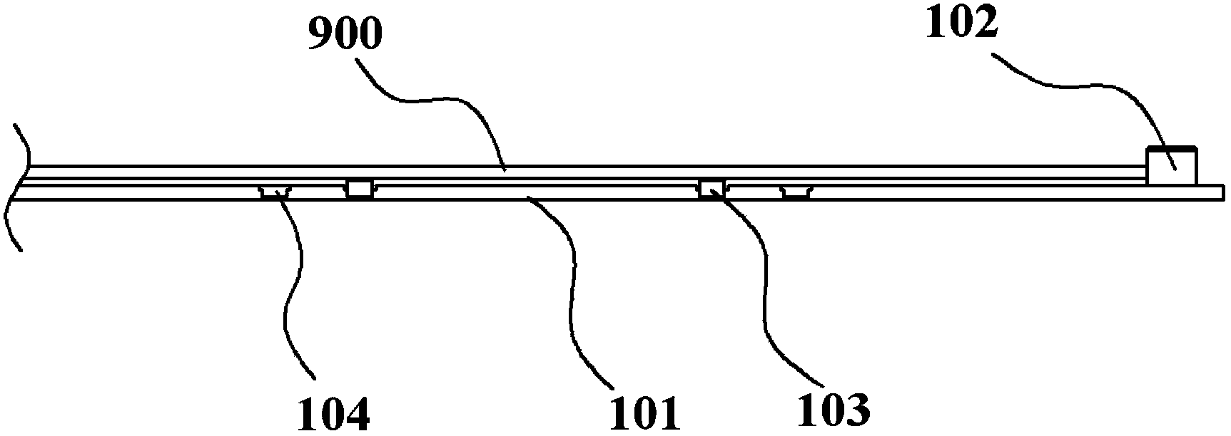
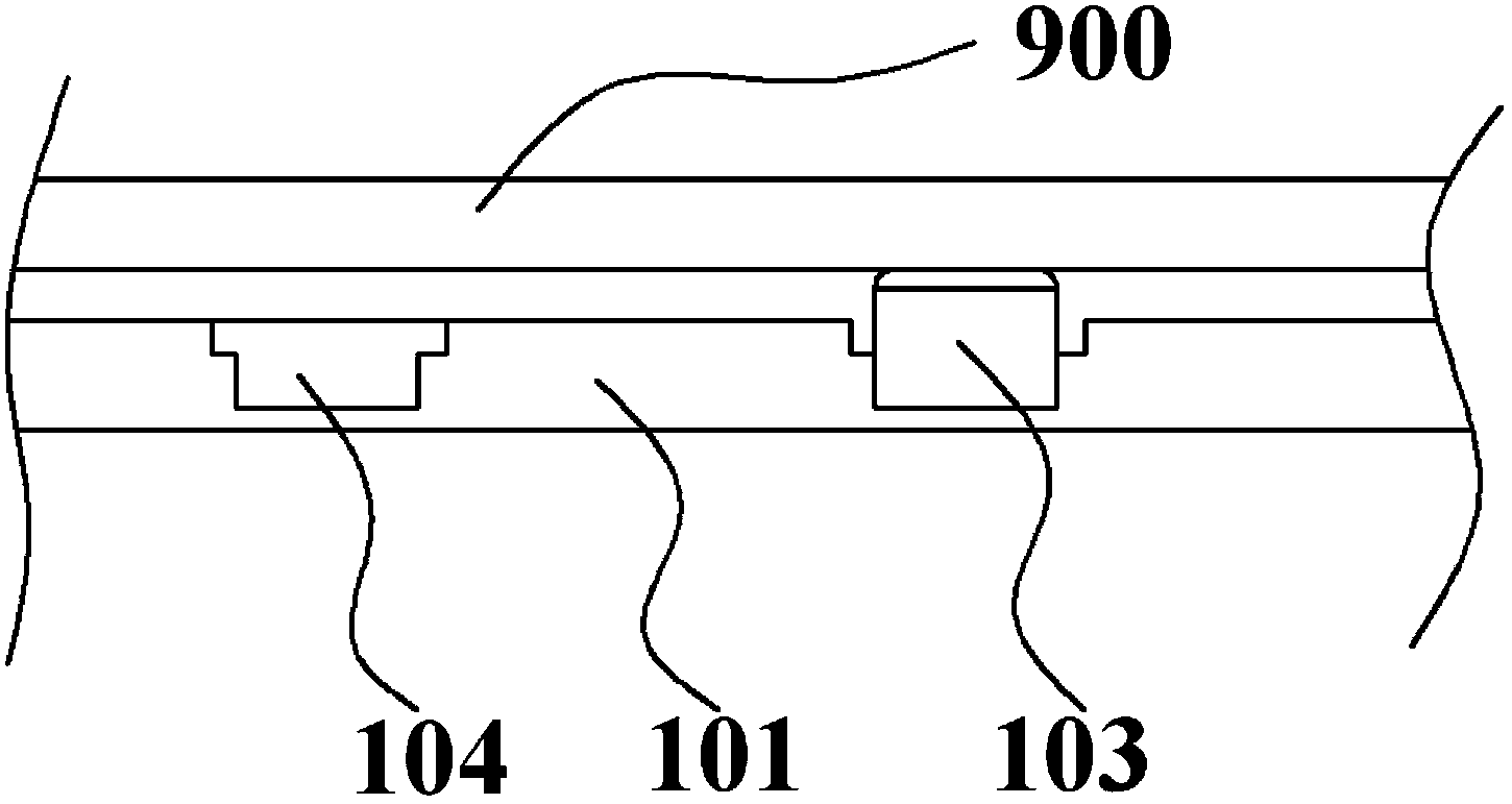
[0040] figure 1 It is a top view of the wafer holding device 100 in the present invention. The wafer clamping device includes a fixed clamping device 100 and a wire telescopic clamping device 200 . figure 2 , image 3 It is a front view of the fixed clamping device 100 .

[0041] The fixed clamping device 100 includes a tray 101 , two side support elements 102 , four raised support pieces 103 , and eight round holes 104 . The shape of the tray 101 is Y-shaped, and four protruding supports 103 are fixed in the circular holes 104 and symmetrically distributed on both sides of the tray 101 . The side support elements 102 are arranged symmetrically at the end positions of the tray 101 .

[0042] Such as image 3 As shown, the protruding supporting member 103 is cylindrical, and the upper part of the cylinder is rounded to avoid scratchi...


PUM


Abstract

A wafer holding device using a pusher rod drawn by strings and springs is provided. The device comprises a tray, four bottom supporting assemblies,two side supporting modules, and a string stretched and shortened holding module. The string stretched and shortened holding module comprises a motor, strings, a pusher rod, two moving clips, two stop blocks and two spring components. The pusher rod drawn by strings and springs is moved along the X-axis by the motor and the spring components, and the wafer is held between the two side supporting modules and the two moving clips. The pressure in the edge of the wafer is provided by the deformation of the springs to hold the wafer. The holding of the wafers with different diameters is carried out by changing the positions of the bump supporters and adjusting the stop blocks so that the problem that only mono-sized wafers could be transferred by the existing transfer structure is solved. The flexibility of the holding for the wafer by spring components serves as a holding buffer, so that the damage of the wafer caused by the impact of the holding force during the wafer-holding process is avoided.

Description

technical field [0001] The invention relates to a wafer clamping device in a semiconductor manufacturing process. Background technique [0002] In the semiconductor manufacturing process, such as wafer cleaning, polishing, etc., there is a large amount of wafer transfer between cassette-cassette and cassette-chamber, so a safe and effective wafer transfer device is designed It is one of the research hotspots in the semiconductor industry. [0003] The wafer transfer device of patent US2006 / 0192400A1 such as Figure 13 shown. Four raised supports 126 are fixed on the tray 124 , the bottom surface of the wafer is in contact with the upper surface of 126 and is supported by 126 , and the movable clip 138 is connected with the cylinder 130 through the connecting rod 136 . By executing the instructions of the external control unit, the cylinder pushes the rod 136 to move linearly forward and backward. The clip 138 moves linearly back and forth synchronously under the action of...

Claims


Application Information

Patent Timeline
Patent Type & Authority Patents(China)
IPC IPC(8): H01L21/687
CPCH01L21/68707
Inventor 朱煜杨开明李鑫汪劲松张鸣徐登峰穆海华尹文生胡金春崔乐卿余东东
Owner TSINGHUA UNIV
Learn More