Wire grid type polarizer and method for manufacturing same

A manufacturing method and polarizer technology, which can be applied in polarizing elements, nonlinear optics, optics, etc., and can solve problems such as image contrast reduction.

Inactive Publication Date: 2012-10-03
ASAHI GLASS CO LTD
View PDF9 Cites 7 Cited by
  • Summary
  • Abstract
  • Description
  • Claims
  • Application Information

AI Technical Summary

Problems solved by technology

If a wire grid polarizer is used in a liquid crystal display device, a liquid crystal panel is disposed on the back side of the wire grid polarizer, so when the s-polarized light reflected by the back side of the wire grid polarizer enters the liquid crystal panel , the contrast of the image displayed on the LCD panel is reduced

Method used


Image

  • Wire grid type polarizer and method for manufacturing same
  • Wire grid type polarizer and method for manufacturing same
  • Wire grid type polarizer and method for manufacturing same

Examples


no. 1 Embodiment approach

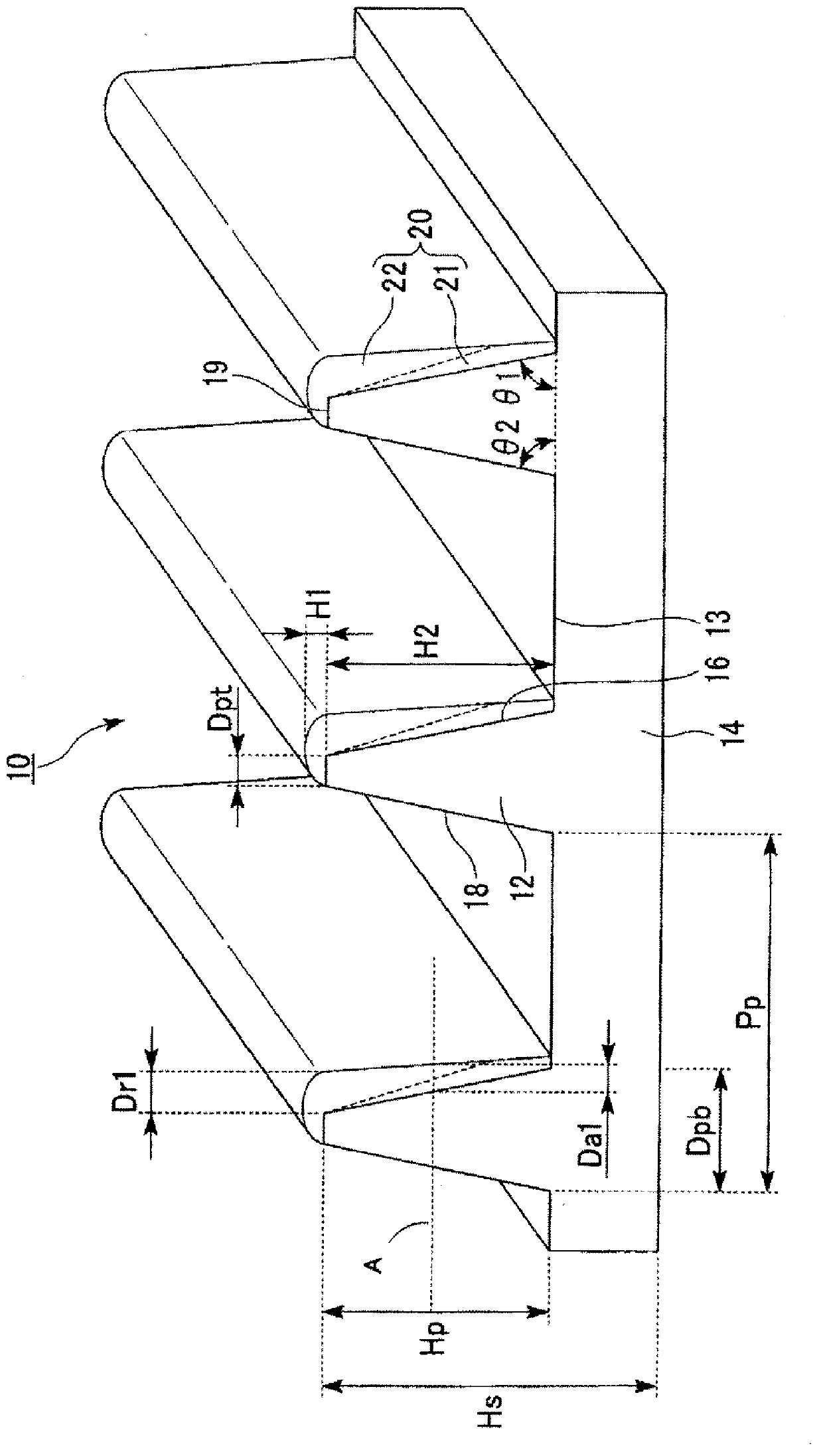
[0101] figure 1 It is a perspective view showing the first embodiment of the wire grid polarizing plate of the present invention. The wire-grid polarizer 10 has a light-transmitting substrate 14 and a first metal layer 20. On the light-transmitting substrate 14, a plurality of ridges 12 with a trapezoidal cross-sectional shape are formed, and the ridges 12 are formed on the ridges. The flat portions 13 of the grooves between the bars 12 are formed on the surface of the light-transmitting substrate 14 parallel to each other and separated by a predetermined pitch Pp. Or metal compound, the first metal layer 20 starts from the position of half the height of the convex strip 12 (at figure 1 Indicated by the dotted line A) to the bottom, the maximum value of the covering thickness is less than the maximum value of the covering thickness from the position of half the height of the raised bar 12 to the top 19 . The first metal layer 20 extends in the longitudinal direction of the r...

no. 2 Embodiment approach

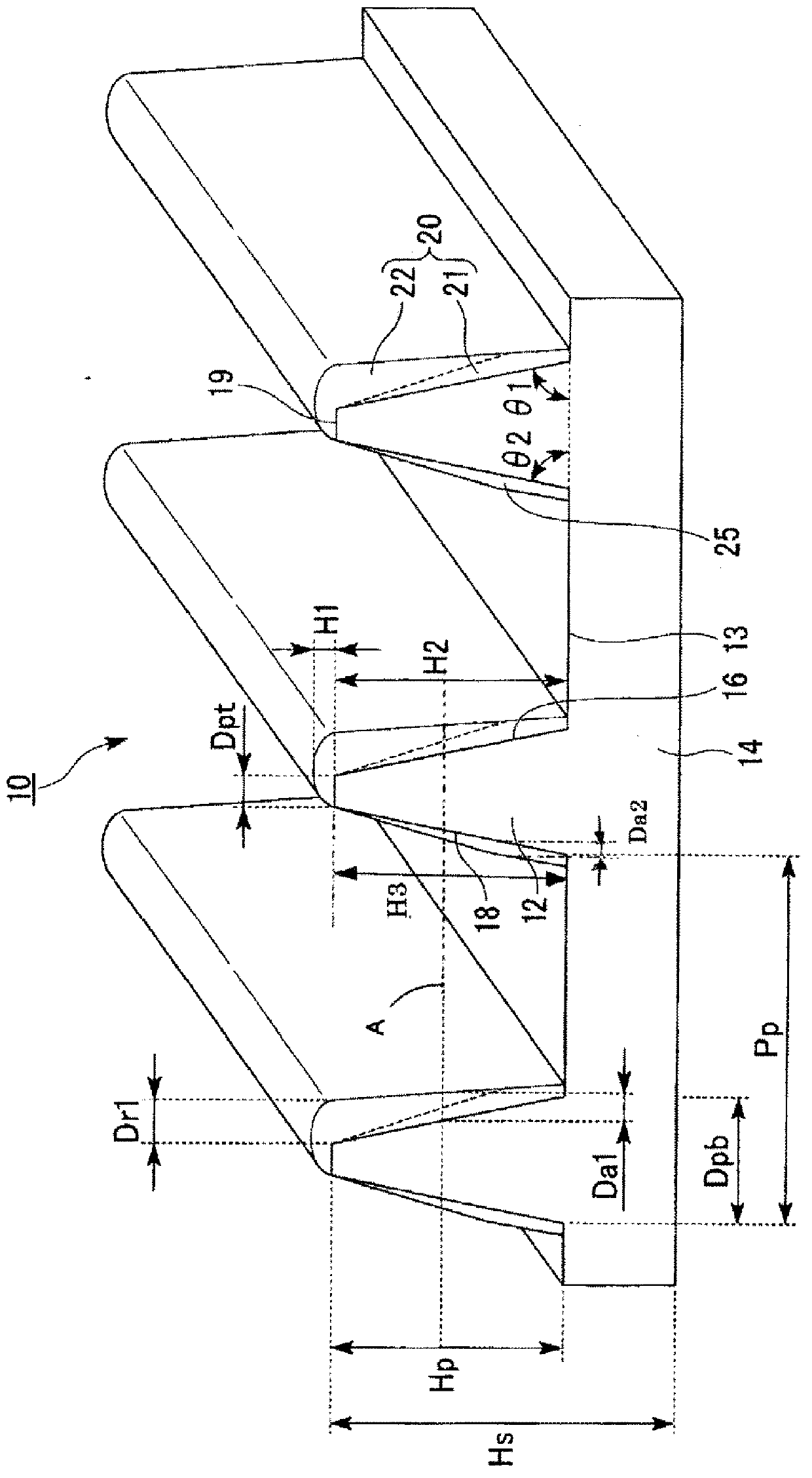
[0123] figure 2 It is a perspective view showing the second embodiment of the wire grid polarizing plate of the present invention. The wire grid polarizing plate 10 has a light-transmitting substrate 14, a first metal layer 20, and a second metal layer 25. On the light-transmitting substrate 14, a plurality of convex lines 12 having a trapezoidal cross-sectional shape are formed. The flat portions 13 of the grooves formed between the protrusions 12 are formed on the surface of the light-transmitting substrate 14 parallel to each other and separated by a predetermined pitch Pp, and the first metal layer 20 covers the first portions of the protrusions 12 . 1 side surface 16 and is made of metal or metal compound, the first metal layer 20 is from the position of half the height of the convex strip 12 (at figure 2 Indicated by dotted line A) the maximum value of the covering thickness to the bottom is less than the maximum value of the covering thickness from the half height po...

no. 3 Embodiment approach

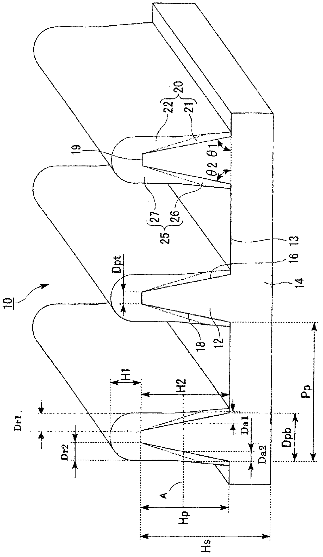
[0130] image 3 It is a perspective view showing a third embodiment of the wire grid polarizing plate of the present invention. The wire grid polarizing plate 10 has a light-transmitting substrate 14, a first metal layer 20, and a second metal layer 25. On the surface of the light-transmitting substrate 14, a plurality of convex lines 12 with a trapezoidal cross-sectional shape are formed. The strips 12 are formed on the surface of the translucent substrate 14 so that the flat portions 13 of the grooves 13 formed between the convex strips 12 are parallel to each other and separated by a predetermined pitch Pp, and the first metal layer 20 covers the convex strips 12. The first side 16 of the ridge 12 is made of metal or a metal compound. image 3 Indicated by dotted line A) the maximum value of the covering thickness to the bottom is less than the maximum value of the covering thickness from the half height position of the raised bar 12 to the top 19, the second metal layer 2...


PUM

PropertyMeasurementUnit
thicknessaaaaaaaaaa
thicknessaaaaaaaaaa
wavelengthaaaaaaaaaa

Abstract

Provided is a wire grid type polarizer having a high polarization degree, a high p-polarized light transmission efficiency, and a low backside surface s-polarized light reflection coefficient, and also provided is a method for manufacturing the wire grid type polarizer. The wire grid type polarizer (10) has: a light-transmissive substrate (14), on the surface of which a plurality of protruded rims (12) are formed in parallel with each other at a predetermined pitch with flat portions (13) formed in between, the protruded rims (12) having a width gradually decreasing from the bottom to the top; and a first metal layer (20) formed of a metal coated on side surfaces of the protruded rims (12), wherein the maximum value of the coated thickness extending from the position corresponding to half the height of the protruded rims (12) to the bottom is smaller than the maximum value of the coated thickness extending from the position corresponding to half the height of the protruded rims (12) to the top portion (19). In the manufacturing method, the first metal layer (20) is formed in such a way that the metal is deposited on the side of a first side surface (16) from a direction forming an angle satisfying the equation tan([theta]<R>1+-10)=(Pp-Dpb / 2) / Hp and then the metal is deposited from a direction forming an angle satisfying the condition [theta]<R>1+5<=[theta]<R>2<=[theta]<R>1+25..

Description

technical field [0001] The present invention relates to a wire-grid polarizer and a method of manufacturing the same. Background technique [0002] As a polarizing plate (also referred to as a polarizing light separating element) exhibiting polarized light separation capability in the visible light range used in image display devices such as liquid crystal display devices, rear projection TVs, and front projectors, there is a wire grid type polarizing plate. [0003] A wire-grid polarizer has a structure in which a plurality of thin metal wires are arranged parallel to each other on a light-transmitting substrate. When the pitch of the metal thin wires is sufficiently shorter than the wavelength of the incident light, the wire grid polarizer transmits the component (that is, p-polarized light) having an electric field vector orthogonal to the metal thin wires in the incident light, The component with the electric field vector parallel to the thin metal wire (ie, s-polarized...

Claims


Application Information

Patent Timeline
Patent Type & Authority Applications(China)
IPC IPC(8): G02B5/30G02F1/1335
CPCG02B5/3058G02B5/30G02F1/1335
Inventor 秋田阳介坂本宽池田康宏樱井宏巳海田由里子志堂寺荣治
Owner ASAHI GLASS CO LTD
Why Eureka
Try Eureka