
Display panel, and display device

A display panel and substrate technology, applied in optics, instruments, nonlinear optics, etc., can solve problems such as not easy to improve contrast, and achieve the effect of reducing black brightness and high contrast

Inactive Publication Date: 2012-10-03
SONY CORP
View PDF6 Cites 7 Cited by
  • Summary
  • Abstract
  • Description
  • Claims
  • Application Information

AI Technical Summary

Problems solved by technology

[0003] However, for a reflective display unit, it is not easy to increase the contrast, so various methods have been proposed in the past

Method used


Image

  • Display panel, and display device
  • Display panel, and display device
  • Display panel, and display device

Examples


Embodiment approach

[0038] IPS (In-Plane Switching) type PDLC for display panels ( Figure 1 to Figure 10) instance

[0039] The configuration of the vertical alignment type PDLC according to the comparative example ( Figure 11 to Figure 13 )

[0040] 2. Modification example

[0041] Example of setting up light guides and edge lights ( Figure 14 )

[0042] Another example of electrode configuration for IPS-type PDLC ( Figure 15 )

[0043] Changes in electrode structure ( Figure 16 to Figure 18 )

[0044] Sets an instance of the color filter ( Figure 19 )

[0045] [1. Implementation method]

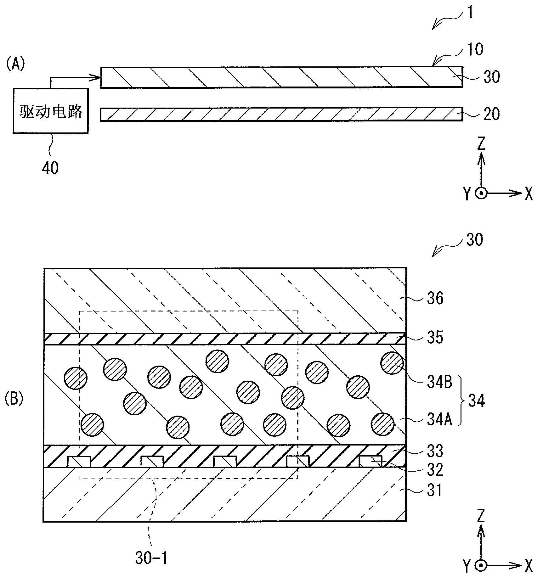
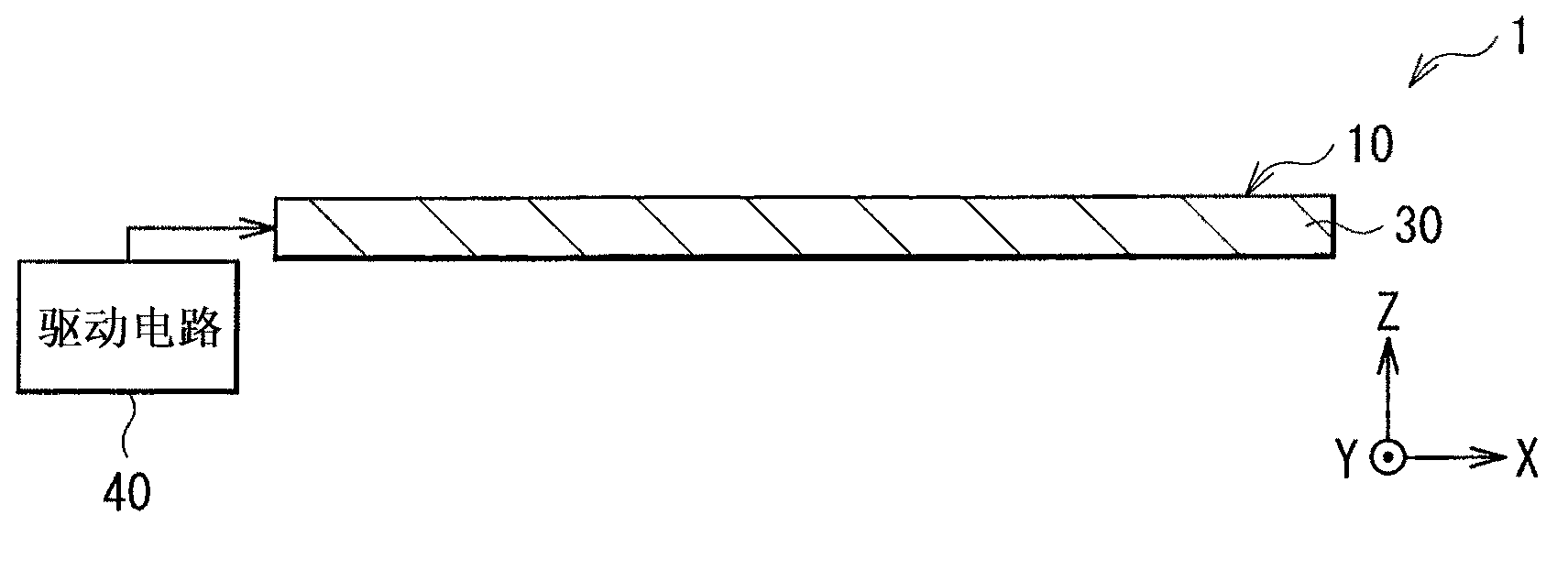
[0046] figure 1 (A) is a sectional view showing an example of a simplified configuration of the display unit 1 according to the embodiment of the present invention. figure 1 (B) is a sectional view showing an example of the configuration of the light modulation device 30, which constitutes figure 1 Part of the display unit 1 shown in (A). It should be noted that figure 1 (A) and (B) are sc...


PUM

PropertyMeasurementUnit
UV radiationaaaaaaaaaa

Abstract

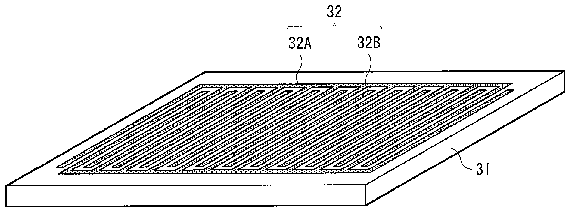
Provided are a display panel and a display device, wherein it is possible to obtain a bright image having high contrast. A display panel (10) is configured from an optical modulation element (30). The optical modulation element (30) is provided with electrodes (32) capable of generating a main electric field in a direction that is parallel to a plane intersecting with the nominal line of a transparent substrate (31), and an optical modulation layer (34) containing particles (34B) and a bulk (34A) having optical anisotropy. The optical axis (AX1, AX2) of the bulk (34A) and of the particles (34B) are parallel or are approximately parallel to the surface of the transparent substrate (31), and, depending on the size of the electric field generated by means of the electrodes (32), are oriented in a different direction from one another or are oriented in the same or approximately the same direction as one another in a plane that is parallel or is approximately parallel to the surface of the transparent substrate (31).

Description

technical field [0001] The present invention relates to a display panel and a display unit including a light modulation device exhibiting scattering and transparency to light. Background technique [0002] In recent years, demand for display units of mobile devices such as mobile phones and electronic papers has increased, and reflective display units have drawn attention. A reflective display unit uses a reflective plate to reflect incident light from the outside to perform display without using a backlight. Therefore, the power consumed by the backlight is saved, which enables the mobile device to be driven for a longer period of time than in the case of using a transmissive type display unit. Also, thereby, not using a backlight allows weight reduction and miniaturization. [0003] However, with a reflective display unit, it is not easy to increase the contrast, and therefore, various methods have been proposed in the past. For example, Patent Document 1 proposes insta...

Claims


Application Information

Patent Timeline
Patent Type & Authority Applications(China)
IPC IPC(8): G02F1/1343G02F1/1334G02F1/13357
CPCG02F1/134363G02F1/134336G02F1/1334G02F1/133524G02F1/13345G02F1/13347G02F1/134381
Inventor 新开章吾奥山健太郎铃木知明蛭子井明高桥雄治西村泰三
Owner SONY CORP
Learn More