Method for removing substrate layers

A substrate and bottom surface technology, applied in the direction of electrical components, semiconductor/solid-state device manufacturing, circuits, etc., can solve problems such as unfavorable crawling characteristics and poor crawling characteristics

Inactive Publication Date: 2012-10-03
RENA
View PDF8 Cites 0 Cited by
  • Summary
  • Abstract
  • Description
  • Claims
  • Application Information

AI Technical Summary

Problems solved by technology

[0012] The etching liquids known in the prior art also have the disadvantage of unfavorable creeping properties, whereby the known liquids with a relatively low viscosity tend to creep up to the edge of the substrate, thus disadvantageously and undesirably Wetting not only the edge but also the top surface of the untreated substrate
It turns out that this poor creep behavior is not only disadvantageous in flat substrates with so-called blind or vias, but even in substrates with structured construction

Method used


Image

  • Method for removing substrate layers
  • Method for removing substrate layers
  • Method for removing substrate layers

Examples


Embodiment Construction

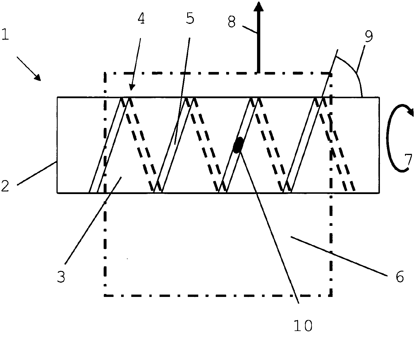
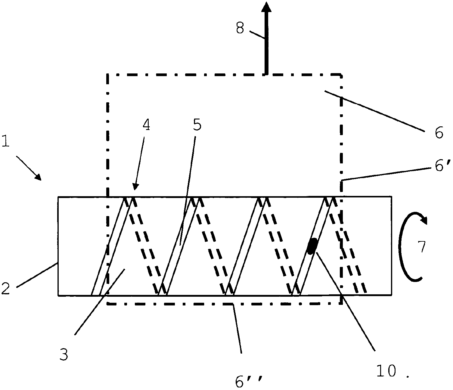
[0086] exist Figure 1A A drum 1 with a thread structure 4 is schematically shown in . The drum 1 is designed as a cylinder and has a base 2 and sides 3 . Other features, such as the axis on which the drum 1 is rotatably mounted and possibly present drive elements, etc. are not shown.

[0087] The thread structure 4 is located on the side 3 . The portion of the thread formation that is blocked by the drum 1 is shown as a dotted line. According to FIG. 1 , the thread structure 4 has a continuous thread line 5 .

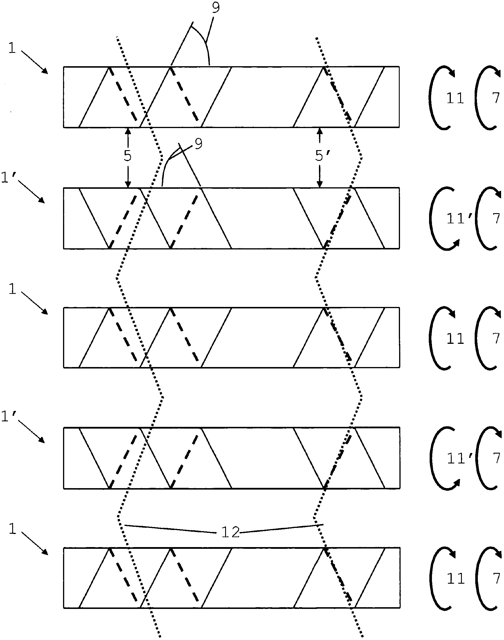
[0088] During the transport of the substrate 6 (shown as a dotted line), the drum 1 is rotated in the direction of rotation 7 . Here too, the conveying direction 8 is formed. The conveying direction is directed parallel to the bottom surface 2 of the drum 1 . In the plan view shown, the thread line 5 forms a lead angle 9 with the side face 3 instead of pointing in the conveying direction 8 . In the figure shown, the lead angle 9 is approximately 70°.

[0089] A...


PUM


Abstract

The present invention relates to a method for the exclusively one-sided wet chemical removal of passivating and/or dielectric oxide layers present on flat substrates, such as in particular silicon wafers, by means of one-sided etching of the underside of a substrate transported horizontally through a tank filled with an etching liquid. When said method is used, there is no need for any protection in the form of a coating or mechanical aid for the face of the substrate that is not to be treated. According to the invention, the etching liquid contains water, hydrofluoric acid and at least one further component selected from the group consisting of sulphuric and phosphoric acid and the alkali, ammonium and organoammonium acid salts and salts thereof, hexafluorosilicic acid, and silicon tetrafluoride.

Description

technical field [0001] The invention relates to a method for wet-chemically removing only one-sided passivation and / or dielectric oxide layers present on flat substrates, such as in particular silicon wafers, by means of The bottom surface of the substrate which is conveyed horizontally through the container filled with the etching solution is single-sided etched. When using this method, it is not necessary to protect the substrate surface not to be treated by means of coatings or mechanical aids. Background technique [0002] In the production of solar cells, for example, the panels obtained by sawing are treated on one or both sides, eg texturing, polishing or sawing damage etching, prior to other production steps which are usually carried out on one side. In this case, passivation layers, such as in particular oxide layers, resulting from a certain process step may have to be removed from the substrate on one side, ie their thickness is reduced or removed entirely on one...

Claims


Application Information

Patent Timeline
Patent Type & Authority Applications(China)
IPC IPC(8): H01L21/00H01L21/306H01L21/311
CPCH01L21/31111H01L21/67086
Inventor 贝恩德-乌韦・桑德尔斯特芬・奎塞尔弗兰克・迪拉海
Owner RENA
Why Eureka
Try Eureka