Manual mechanical oil-pouring device

A manual machine and oil pouring technology, used in packaging, emptying containers, bottle filling, etc., can solve the problems of high labor intensity and low work efficiency, and achieve the effect of reducing labor intensity and improving work efficiency.

Inactive Publication Date: 2012-10-10
王晓彬
View PDF0 Cites 23 Cited by
  • Summary
  • Abstract
  • Description
  • Claims
  • Application Information

AI Technical Summary

Problems solved by technology

[0003] The purpose of the present invention is to provide a manual mechanical oil pouring device to solve the problems of low work efficiency and high labor intensity in the prior art

Method used


Image

  • Manual mechanical oil-pouring device

Examples


Embodiment Construction

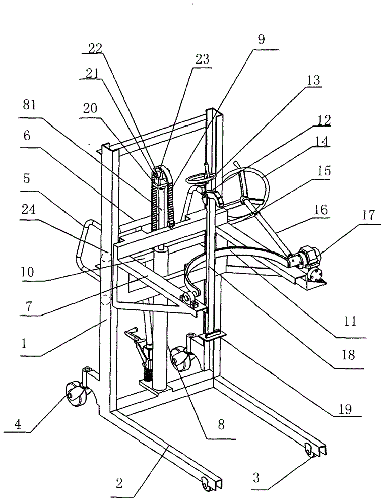
[0011] see figure 1 , the present invention relates to a manual mechanical oil pouring device, comprising a door frame 1, a base 2, a front wheel 3, a steering wheel 4 and a handrail 5, a base 2 is connected to the bottom end of the door frame 1, and the front end of the base 2 Front wheels 3 and steering wheels 4 are respectively installed at the bottom and rear end of the door frame 1, and handrails 5 are installed on the top of the door frame 1. It is characterized in that: a lifting frame 7 is installed on the door frame 1, and the lifting frame 7 corresponds to the base 1 and is located on the same side of the door frame 1. The lifting frame 7 moves up and down on the door frame 1 through the drive of the lifting mechanism, and also includes a half round hoop 11, one end of which is rotated Installed on the lifting frame 7, the other end is connected with a turning mechanism, and a clamping mechanism is installed on the semicircular hoop 11.

[0012] The lifting mechanis...


PUM


Abstract

The invention relates to a manual mechanical oil-pouring device which comprises a portal frame, a pedestal, front wheels, steering wheels and armrests, wherein the bottom end of the portal frame is connected with the pedestal; the front wheels and the steering wheels are respectively installed at the bottom of the front end and the rear end of the pedestal; and the armrests are installed at the upper part of the portal frame. The manual mechanical oil-pouring device is characterized in that a lifting frame corresponding to the pedestal is installed on the portal frame and is driven by a lifting mechanism to move up and down on the portal frame; the manual mechanical oil-pouring device further comprises a semicircle hoop; one end of the semicircle hoop is rotationally installed on the lifting frame; the other end of the semicircle hoop is connected with a turnover mechanism; and a clamping mechanism is installed on the semicircle hoop. The manual mechanical oil-pouring device has the advantages that through the organic coordination of the clamping mechanism, the lifting mechanism and the turnover mechanism, oil in an oil drum is directly poured out after the oil drum is leaned, so as to replace an oil-pumping mode in the prior art. Therefore, the manual mechanical oil-pouring device improves work efficiency and reduces labor intensity.

Description

technical field [0001] The invention relates to an oil pouring device, in particular to a manual mechanical oil pouring device. Background technique [0002] The oil contained in the oil barrel of the prior art usually uses the oil pump to extend into the barrel to extract the oil, and then disperses the oil. However, because the amount of oil pumped by the oil pump is limited each time, it needs to be extracted many times. , low work efficiency and high labor intensity. Contents of the invention [0003] The purpose of the present invention is to provide a manual mechanical oil pouring device to solve the problems of low work efficiency and high labor intensity in the prior art. The technical solution of the present invention is: a manual mechanical oil pouring device, including a door frame, a base, a front wheel, a steering wheel and a handrail, a base is connected to the bottom of the door frame, the bottom of the front end of the base and the rear end Front wheels a...

Claims


Application Information

Patent Timeline
Patent Type & Authority Applications(China)
IPC IPC(8): B65G65/23
Inventor 王晓彬王光明郭志刚
Owner 王晓彬
Why Eureka
Try Eureka